Band gap reference voltage circuit

A reference voltage and circuit technology, applied in the direction of adjusting electrical variables, control/regulation systems, instruments, etc., can solve the problems of sensitivity to power supply voltage rise rate, circuit failure, and inability to achieve full temperature compensation, etc., to achieve the effect of eliminating sensitivity

Inactive Publication Date: 2012-03-14
张伟
View PDF4 Cites 2 Cited by
  • Summary
  • Abstract
  • Description
  • Claims
  • Application Information

AI Technical Summary

Problems solved by technology

Adjust R2/R1 in the design so that Vref must be within a certain voltage range to achieve a parabolic curve for temperature changes, which prevents full temperature compensation for reference voltages outside the voltage range, which causes problems in multi-reference voltag

Method used


Image

  • Band gap reference voltage circuit
  • Band gap reference voltage circuit
  • Band gap reference voltage circuit

Examples


Embodiment 1

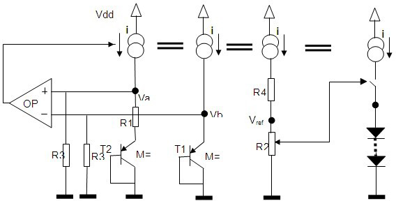
[0017] see figure 1 , the present invention relates to a multi-reference voltage output bandgap circuit, the voltage VDD is divided into three circuits: the first circuit is connected with the emitter of the triode T2 through the resistor R1, the base of T2 is connected with the collector and grounded; the second circuit is connected with the collector The emitter of the triode T1 is connected, the base of T2 is connected to the collector and then grounded; the third path is grounded through the resistors R4 and R2, and the voltage Vref output point is between the resistors R4 and R2; the first path and the second path are also connected to the ground. The input terminals of the operational amplifier OP are respectively connected, and the input terminals of the OP are all grounded through the resistor R3, and the output terminals directly control the constant current source circuit.

Embodiment 2

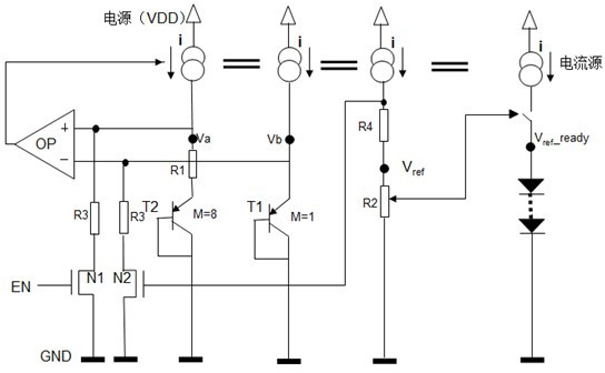
[0019] see figure 2 The difference between the second embodiment and the first embodiment is that the input terminal of the operational amplifier is grounded through the MOS transistors N1 and N2 after passing through R3, and the control terminal G of the N2 is connected to the above-mentioned third loop.


PUM


Abstract

The invention relates to a band gap reference voltage circuit. The voltage VDD is divided into three paths; the first path is connected with an emitter of a triode T2 through a resistor R1, and a base of the T2 is connected with a collector and then is grounded; the second path is connected with an emitter of a triode T1, and a base of the T1 is connected with a collector and then is grounded; the third path is grounded through resistors R4 and R2, and a voltage Vref output point is positioned between the resistor R4 and the resistor R2; and the first path and the second path are connected to the input end of an operational amplifier OP, and the input end of the OP is grounded through a resistor R3, and the output end of the OP directly controls a constant current source circuit. The band gap reference voltage circuit has a startup enhancing function.

Description

technical field [0001] The invention relates to a bandgap reference voltage circuit. Background technique [0002] Power converters, such as DC-DC or AC-DC converters, typically consume more energy when operating at full capacity. The power consumption of this semiconductor device will cause the temperature to rise rapidly, causing the drift of the reference voltage of the chip, thereby causing the instability of the output voltage. DC voltages are particularly susceptible to DC voltage converters and power amplifiers because higher output voltages and higher output currents require more stable power supply systems. [0003] A bandgap reference circuit can be used to alleviate problems related to temperature drift. This usually consists of a temperature compensation unit, a Brakow unit, and a transistor or resistor with a negative temperature coefficient. Many different types of bandgap circuits have been used. Example: The voltage difference between two diodes with the ...

Claims


Application Information

Patent Timeline
IPC IPC(8): G05F3/30
Inventor 张伟
Owner 张伟
Why Eureka
Try Eureka