A DC power supply with energy closed loop control

A technology of DC power supply and closed-loop control, which is applied in the direction of control/regulation system, conversion of DC power input to DC power output, electrical components, etc. It can solve problems such as poor dynamic performance, reduce complexity, and realize the effect of dynamic adjustment time

Active Publication Date: 2018-12-21
HARBIN ENG UNIV
View PDF8 Cites 14 Cited by
  • Summary
  • Abstract
  • Description
  • Claims
  • Application Information

AI Technical Summary

Problems solved by technology

[0003] Aiming at the above-mentioned prior art, the technical problem to be solved by the present invention is to provide a method for the problem of poor dynamic performance of the DC power output voltage control strategy based on the traditional PID controller, and realize the control of the DC power output voltage through the energy closed loop. control, thereby improving its dynamic performance of the energy closed-loop control of the DC power supply

Method used


Image

  • A DC power supply with energy closed loop control

Examples


Embodiment approach 1

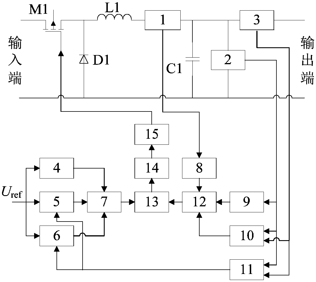
[0030] The main circuit adopts a Buck circuit, and the design and selection methods of the power electronic device M1, inductor L1, capacitor C1, freewheeling diode D1 and other devices are exactly the same as those of the existing standard Buck circuit;

[0031] The inductor current detection circuit 1 and the output current detection circuit 3 can be designed and implemented with reference to various existing circuits with current detection and signal transmission functions, for example, Hall-type current sensors can be used supplemented by corresponding signal processing circuits.

[0032] The capacitive voltage detection circuit 2 can be designed and implemented with reference to various existing circuits with voltage detection and signal transmission functions, for example, a Hall-type voltage sensor can be used supplemented by a corresponding signal processing circuit.

[0033] The expected capacitor energy storage calculation circuit 4 is realized by a circuit capable of...

Embodiment approach 2

[0046] The main circuit adopts other topology forms of Buck circuit, or other forms of DC / DC conversion circuits.

[0047] When the number of capacitive and inductive devices in the main circuit, the placement position and figure 1 When the main circuits shown are different, each capacitor needs to have a corresponding terminal voltage detection circuit, as well as a corresponding expected energy storage calculation circuit and an actual energy storage calculation circuit; each inductor needs a corresponding current detection circuit, and a corresponding The expected energy storage calculation circuit and the actual energy storage calculation circuit; the number and operation rules of the input channels of the expected total energy calculation circuit 7 and the actual total energy calculation circuit 12 also need to be adjusted accordingly.

[0048] Other design methods are the same as the first implementation method.


PUM


Abstract

The invention relates to a DC power supply controlled by an energy closed loop, comprising a main circuit and a control circuit. The main circuit is a standard Buck circuit. The control circuit comprises: Inductance Current Detection Circuit, capacitance voltage detection circuit, output current detection circuit, Circuit for calculate energy storage of desired capacitance, an expected inductanceenergy storage calculation circuit, an expected load energy consumption calculation circuit, an expected total energy calculation circuit, an actual inductance energy storage calculation circuit, an actual capacitance energy storage calculation circuit, an actual load energy consumption calculation circuit, a load identification circuit, an actual total energy calculation circuit, an operation circuit, a controller circuit, and a PWM signal circuit. As that invention weaken the sensitivity of the dynamic performance of the output of the power supply to the value of the control parameter, the complexity of the controller parameter design is reduce, and the overshoot and oscillation phenomena of the voltage and the current are restrained, at the same time, the optimization of the dynamic adjustment time is realized.

Description

technical field [0001] The invention relates to a direct current power supply, in particular to a direct current power supply which realizes output voltage control by energy closed loop. Background technique [0002] DC power supplies are widely used in fields such as computers, household appliances, energy and new automobiles. At present, most of these DC power supplies adopt the voltage and current double closed-loop control strategy based on the traditional PID controller, or the voltage single closed-loop control strategy to obtain stable voltage output, but whether it is voltage, current double closed-loop control or voltage single closed-loop control, in During the dynamic adjustment process of the output voltage, either there is a problem of too long adjustment time, or there are obvious overshoot and oscillation phenomena. Although good dynamic performance can be obtained within a certain range through reasonable design of controller parameters, when the operating c...

Claims


Application Information

Patent Timeline
Patent Type & Authority Applications(China)
IPC IPC(8): H02M3/158H02M1/34
CPCH02M1/34H02M3/1584H02M1/348
Inventor 张强魏家植何昕武保成董童鹤温剑桥王禹霖宋世豪
Owner HARBIN ENG UNIV
Why Eureka
Try Eureka