Assembly error acquisition method meeting actual working conditions

A technology of assembly error and actual working conditions, applied in the direction of instruments, geometric CAD, calculation, etc., can solve the problems of inaccuracy, seldom consider the local deformation of the parts surface, and the big difference between the analysis and prediction results and the actual situation, so as to improve the The effect of forecast accuracy

Inactive Publication Date: 2018-04-20
HUAZHONG UNIV OF SCI & TECH
View PDF3 Cites 9 Cited by
  • Summary
  • Abstract
  • Description
  • Claims
  • Application Information

AI Technical Summary

Problems solved by technology

[0002] Under complex working conditions, complex mechanical products are easily affected by temperature, centrifugal force, gravity, etc. during the work of the whole machine and parts, resulting in a large difference between the corresponding assembly accuracy and the theoretical prediction value, thus affecting the mechanical service performance and service of the whole machine life
Therefore, it is necessary to introduce the theory and method of assembly error construction under actual working conditions to predict the impact of actual working conditions on the assembly accuracy of the system end, and reasonably determine the accuracy of parts, otherwise it will be difficult to meet the performance requirements of the product
[0003] In recent years, scholars at home and abroad have done a lot of research in the field of tolerance modeling and achieved some research results. However, when analyzing the tolerance of the 3D model of the product, they ignore the actual working environment of the product (such as the product bears various loads and temperature change, etc.), so that the analysis and prediction results are quite different from the actual situation.
The traditional assembly error analysis and modeling method is mainly to establish a screw expression such as a screw model for the variation range of the surface of the rigid part within the tolerance range, as described in the book "Theory and practice of 3-D tolerance for assembly" Introduced methods, these rarely take into account the local deformation of the component surface in the actual working conditions
However, most of the current methods considering the thermal and force deformation of parts only consider the maximum deformation, and cannot accurately simulate the deformation of each point on the surface of the part, especially when calculating the gap between two mating planes, it is impossible to accurately calculate the deformation of the two planes. The corresponding gap between each point
The requested result is too simple and not precise enough

Method used


Image

  • Assembly error acquisition method meeting actual working conditions
  • Assembly error acquisition method meeting actual working conditions
  • Assembly error acquisition method meeting actual working conditions

Examples


Embodiment Construction

[0036] In order to make the objectives, technical solutions and advantages of the present invention clearer, the following further describes the present invention in detail with reference to the accompanying drawings and embodiments. It should be understood that the specific embodiments described herein are only used to explain the present invention, but not to limit the present invention. In addition, the technical features involved in the various embodiments of the present invention described below can be combined with each other as long as they do not conflict with each other.

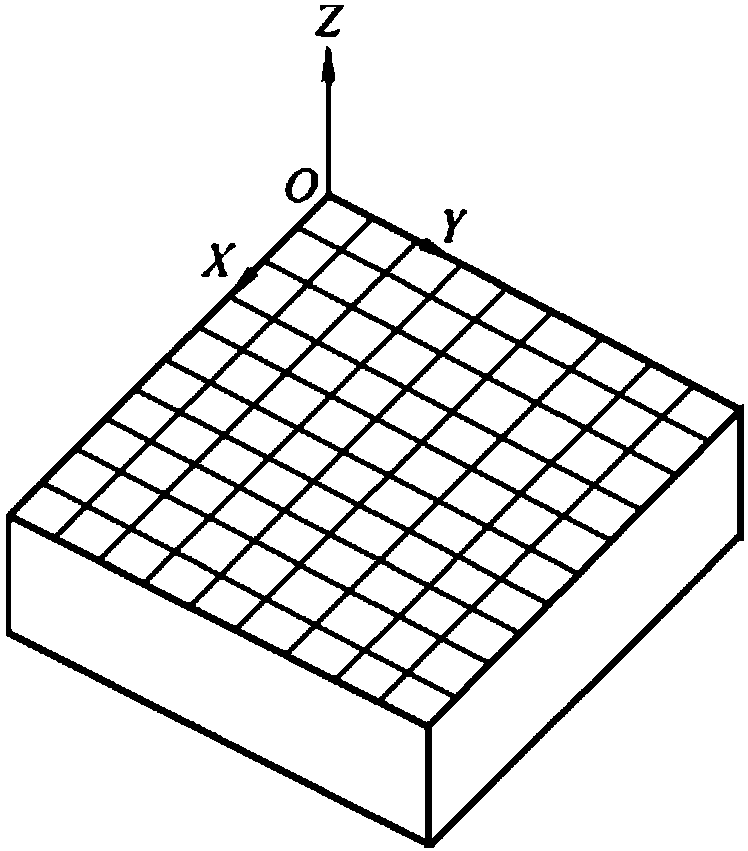
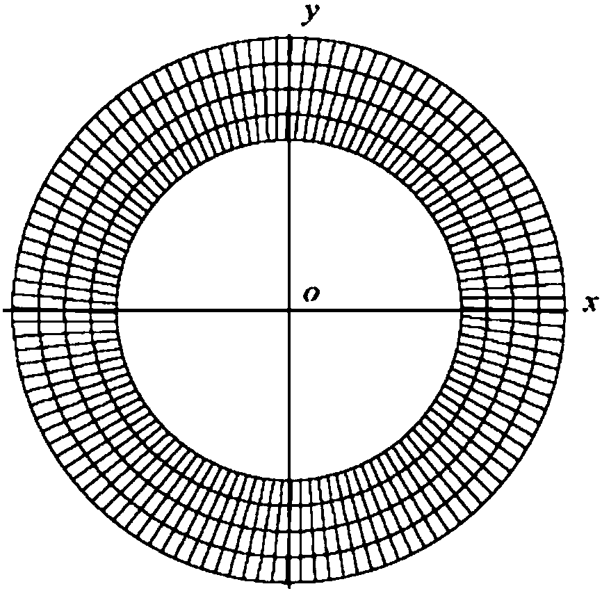
[0037] Refer to Figure 1~ Figure 5 In the present invention, an azimuth propeller blade is taken as an example. The entire blade bearing assembly includes the blade root 4, the crank pin disk 6, the hub body 7 and the O-ring 5. The blade root 4 and the crank pin 6 are connected by bolts, and the hub body 7 is sandwiched between the two. The O-shaped seal ring 5 is placed in the O-shaped groove of th...


PUM


Abstract

The invention belongs to the field of mechanical manufacturing product assembly error modeling and discloses an assembly error acquisition method meeting actual working conditions. The method comprises the steps that (1) an assembly error spinor model based on a corrected Jacobian spinor model is established; (2) discretization is performed on part surfaces; (3) finite element software is utilizedto load a temperature field and add a stress field load, and part surface deformation is obtained; (4) the part surface deformation meeting the actual working conditions is obtained; and (5) after part surface node deformation meeting the actual working conditions is obtained, subtraction is performed on node coordinate deformation corresponding to upper contact surfaces and lower contact surfaces of combination surfaces, and then surface true assembly errors meeting the actual working conditions can be obtained. Through the method, clearance between corresponding nodes of matching surfaces can be predicted quite precisely, influences of the actual working conditions on the assembly errors are fully considered, and assembly error prediction precision is greatly improved.

Description

Technical field [0001] The invention belongs to the field of assembly error modeling of mechanical manufacturing products, and more specifically, relates to an assembly error acquisition method oriented to actual working conditions. Background technique [0002] Complex mechanical products are easily affected by temperature, centrifugal force, gravity, etc. during the work of complex mechanical products under complex working conditions. As a result, the corresponding assembly accuracy may differ greatly from the theoretical prediction value, thereby affecting the mechanical service performance and service of the whole machine life. Therefore, it is necessary to introduce the theory and method of assembly error construction under actual working conditions to predict the impact of actual working conditions on the assembly accuracy of the system end, and to reasonably determine the accuracy of parts, otherwise it will be difficult to meet the performance requirements of the product....

Claims


Application Information

Patent Timeline
Patent Type & Authority Applications(China)
IPC IPC(8): G06F17/50
CPCG06F30/17G06F30/23
Inventor 曾文会饶运清王鹏龙晨曦陈立
Owner HUAZHONG UNIV OF SCI & TECH
Why Eureka
Try Eureka