Ventilation hole structure for rainproof type relay

A relay and ventilation hole technology, applied in relays, electromagnetic relays, electromagnetic relay detailed information, etc., can solve the problems affecting the working performance of the internal parts of the relay, reducing the waterproof ability of the relay, etc., to achieve the effect of simple design and improved rainproof ability

Active Publication Date: 2018-04-20
XIAMEN HONGFA AUTOMOTIVE ELECTRONICS
View PDF5 Cites 4 Cited by
  • Summary
  • Abstract
  • Description
  • Claims
  • Application Information

AI Technical Summary

Problems solved by technology

The air hole is designed as a straight hole, which is conducive to the automatic operation of the process of spotting glue or hot riveting to seal the air hole, and improves production efficiency. However, the structure of this air hole greatly reduces the waterproof ability of the relay.
[0005] In order to realize the waterproof function of the relay, the existing technology is to set the vent hole on the side wall of the casing. However, with this vent hole structure, when the glue is dispensed, the photoresist is easy to flow into the casing from the vent hole on the side wall of the casing, which affects The working performance of the internal parts of the relay

Method used


Image

  • Ventilation hole structure for rainproof type relay
  • Ventilation hole structure for rainproof type relay
  • Ventilation hole structure for rainproof type relay

Examples


Embodiment 1

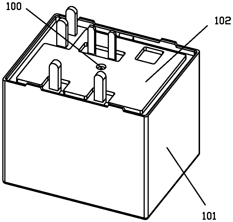
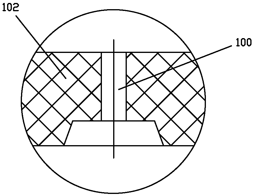
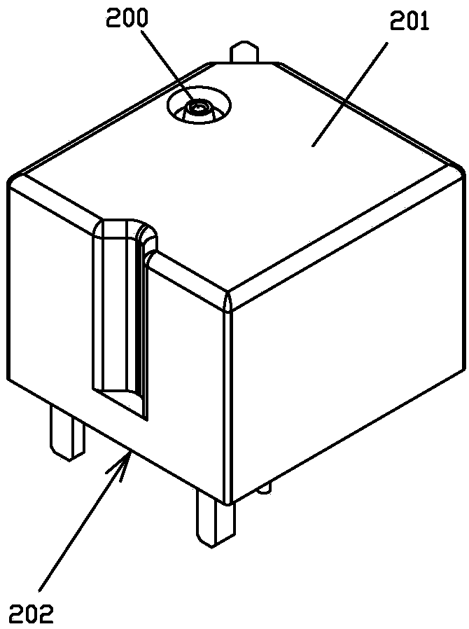
[0039] see Figure 5 to Figure 11 As shown, the ventilation hole structure of a rainproof relay of the present invention includes a housing 1 and a base 2; the housing 1 has a cavity 11 with an opening facing downward so as to accommodate the internal parts of the relay (such as the magnetic circuit of the relay parts, pushing parts, dynamic and static contacts, etc.); the base 2 is embedded in the bottom of the shell 1, that is, the base 2 is embedded in the bottom of the inner cavity 11 of the shell 1; The top extends downwards to form a vertical rib 12, the bottom surface of the rib 12 is provided with a groove 3 with the opening facing downward, and a through hole 13 is provided on one of the side walls of the housing 1, and the through hole 13 is connected to the The grooves 3 are connected, and the grooves 3 are configured as a structure with a large mouth and a small interior, and the through hole 13 and the groove 3 form a vent hole of the relay.

[0040] In this embo...

Embodiment 2

[0051] see Figure 12 to Figure 14 As shown, the air hole structure of a rainproof relay of the present invention differs from that of Embodiment 1 in that the inclined groove 32 is arranged on the outside, and the straight groove 31 is arranged on the inside.

Embodiment 3

[0053] see Figure 15 As shown, the air hole structure of a rainproof relay of the present invention differs from the first embodiment in that the housing 1 is a single shell structure.


PUM


Abstract

The invention discloses a ventilation hole structure for a rainproof type relay. The ventilation hole structure for the rainproof type relay comprises a shell and a base; the shell is provided with acavity having a downward opening, so that internal parts of the relay are contained; the base is embedded at the bottom of the shell; a vertical raised rib downwardly extending along the top is arranged outside one side wall of the shell; a groove having a downward opening is arranged on the bottom end face of the raised rib; a through hole is arranged in one side wall of the shell; the through hole is communicated with the groove; furthermore, the groove is set to a structure having a large mouth and a small internal part; and the through hole and the groove form the ventilation hole of the relay. According to the ventilation hole structure for the rainproof type relay disclosed by the invention, the structure of the ventilation hole is improved; therefore, the structure is simple; a module can be conveniently released when a part is produced; furthermore, optical cement can be prevented from flowing into the interior of the relay from the small hole at the broadside of the shell; andthus, the use performance of the relay is ensured.

Description

technical field [0001] The invention relates to a relay, in particular to a vent hole structure of a rainproof relay. Background technique [0002] The relay usually includes a magnetic circuit part, a pushing part, a moving spring part, a static spring part, a housing and a base. And the inner cavity of the housing accommodates the internal parts of the relay such as the magnetic circuit part, the pushing part, the moving spring part, and the moving and static contacts of the static spring part. [0003] The relays in the prior art are usually provided with vent holes, and the function of setting the vent holes is to exhaust the air when the plastic sealant is dried after the relay is clicked, so as to prevent the expansion gas inside the relay from blowing the uncured plastic sealant to the top of the uncured plastic sealant during heat drying. Open, forming air grooves, affecting the sealing performance of the product. [0004] Usually, the vent hole of the relay is gen...

Claims


Application Information

Patent Timeline
Patent Type & Authority Applications(China)
IPC IPC(8): H01H50/02
CPCH01H50/023
Inventor 舒志刚
Owner XIAMEN HONGFA AUTOMOTIVE ELECTRONICS
Why Eureka
Try Eureka