Photovoltaic solar energy support device

A photovoltaic solar energy and support device technology, which is applied to the support structure of photovoltaic modules, photovoltaic modules, photovoltaic power generation, etc., can solve the problems that photovoltaic solar panels do not have protective structures, cannot be protected by photovoltaic solar panels, and are easily damaged. Achieve the effect of unique structure, improve the scope of use, and increase the rain-shielding area

Active Publication Date: 2020-02-21
江天科技有限公司
View PDF6 Cites 3 Cited by
  • Summary
  • Abstract
  • Description
  • Claims
  • Application Information

AI Technical Summary

Problems solved by technology

[0003] Solar photovoltaic panels generally need to be supported by mounting brackets during installation, but traditional photovoltaic solar panels do not have a protective structure. When it rains or is not used for a long time, the photovoltaic solar panel cannot be protected to a certain extent, making the photovoltaic solar panel easy to damage. Reduced service life

Method used


Image

  • Photovoltaic solar energy support device
  • Photovoltaic solar energy support device
  • Photovoltaic solar energy support device

Examples


Embodiment 1

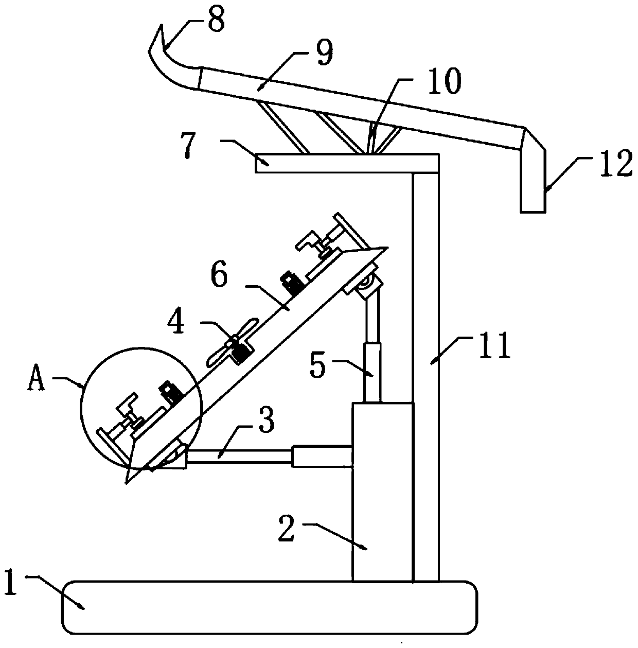
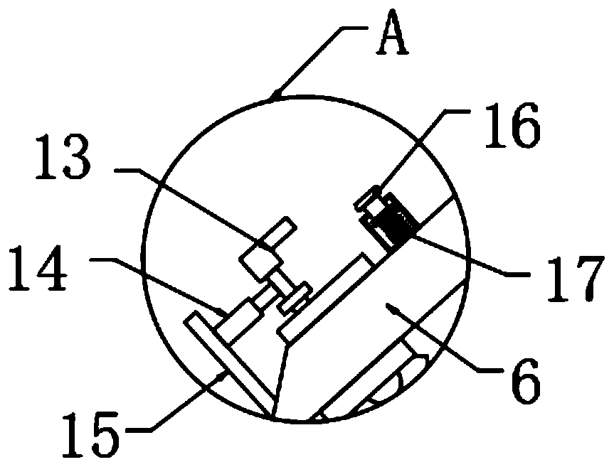
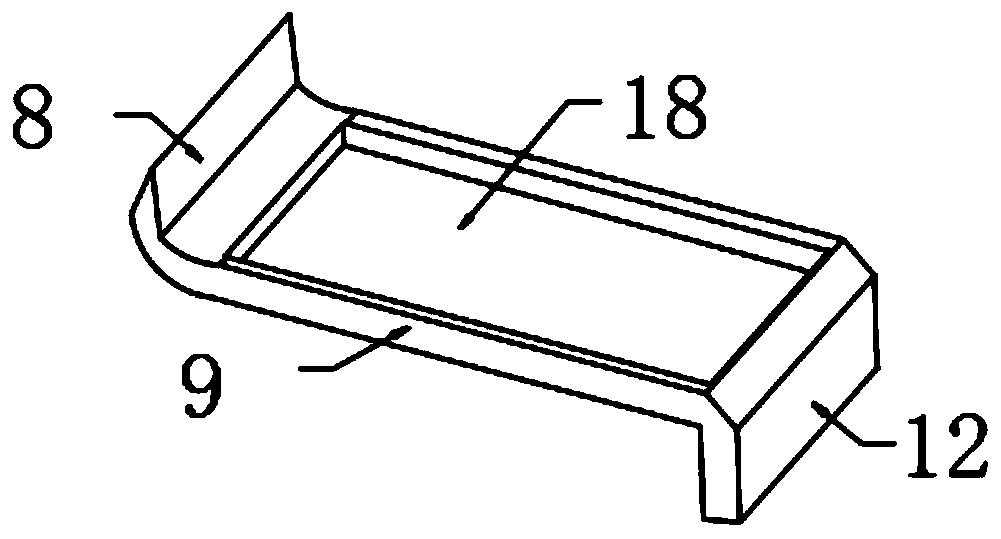
[0029] refer to Figure 1-4 , a support device for photovoltaic solar energy, including a base 1, a support rod 11 is fixed on the top outer wall of the base 1 by screws, and a horizontal plate 7 is fixed on the top outer wall of the support rod 11 by screws, and the top outer wall of the horizontal plate 7 is welded with a support frame 10, and the top outer wall of the support frame 10 is fixed with a rain shield 9 by screws, one side of the top outer wall of the rain shield 9 is fixed with an arc-shaped rain shield 8 by screws, and the other side of the top outer wall of the rain shield 9 The guide groove 12 is fixed by screws, the support member 2 is fixed on the top outer wall of the base 1 by screws, and the first hydraulic rod 3 is fixed on one side outer wall of the support member 2 by screws.

[0030] In the present invention, the top outer wall of the rain shield 9 is provided with a groove 18, the top outer wall of the support member 2 is fixed with a second hydraul...

Embodiment 2

[0034] refer to Figure 5 , a support device for photovoltaic solar energy, including a base 1, a support rod 11 is fixed on the top outer wall of the base 1 by screws, and a horizontal plate 7 is fixed on the top outer wall of the support rod 11 by screws, and the top outer wall of the horizontal plate 7 is welded with a support frame 10, and the top outer wall of the support frame 10 is fixed with a rain shield 9 by screws, one side of the top outer wall of the rain shield 9 is fixed with an arc-shaped rain shield 8 by screws, and the other side of the top outer wall of the rain shield 9 The guide groove 12 is fixed by screws, the top outer wall of the base 1 is fixed with a support 2 by screws, and the first hydraulic rod 3 is fixed on one side of the support 2 by screws, and the top outer wall of the rain shield 9 is provided with a groove 18. The top outer wall of the support 2 is fixed with a second hydraulic rod 5 by screws, and the other end of the second hydraulic rod...


PUM


Abstract

The invention belongs to the technical field of supporting devices, and in particular relates to a photovoltaic solar energy support device. For the problem that a protection structure is unavailable,the device provided by the invention comprises a base. A supporting rod is arranged on the outer wall of the top of the base. A transverse plate is arranged on the outer wall of the top of the supporting rod. A supporting frame is arranged on the outer wall of the top of the transverse plate. A flashing board is arranged on the outer wall of the top of the supporting frame. An arc-shaped flashing board is arranged on one side of the outer wall of the top of the flashing board. A guide groove is formed on the other side of the outer wall of the top of the flashing board. A supporting piece is arranged on the outer wall of the top of the base, and a first hydraulic rod is arranged on the outer wall of one side of the supporting piece. According to the invention, the flashing board, the arc-shaped flashing board, a mounting frame and the guide groove are arranged; the guide groove is formed on the other side of a photovoltaic solar panel; rainwater can be guided to the other end of thephotovoltaic solar panel; in addition, the arc-shaped flashing board is unique in structure; the rain shielding area can be increased through the arc-shaped structure; the rain shielding effect is improved; and the service life of the solar photovoltaic panel is prolonged.

Description

technical field [0001] The invention relates to the technical field of support devices, in particular to a support device for photovoltaic solar energy. Background technique [0002] Solar photovoltaic power generation system is a new type of power generation system that uses the photovoltaic effect of solar cell semiconductor materials to directly convert solar radiation energy into electrical energy. There are two modes of independent operation and grid-connected operation. Independently operating photovoltaic power generation systems require batteries as energy storage devices. They are mainly used in remote areas without grids and areas with scattered populations. The cost of the entire system is high. In areas with public power grids, photovoltaic power generation systems are connected to the grid and run in parallel. Save the storage battery, not only can greatly reduce the cost, but also has higher power generation efficiency and better environmental protection perfor...

Claims


Application Information

Patent Timeline
Patent Type & Authority Applications(China)
IPC IPC(8): H02S40/10H02S20/30
CPCH02S40/10H02S20/30Y02E10/50
Inventor 陈万通
Owner 江天科技有限公司
Why Eureka
Try Eureka