
A dynamic power flow analysis method and a dynamic power flow analysis system

A technology of dynamic power flow and analysis method, applied in the field of energy Internet, which can solve problems such as no description, no mention of users, no consideration of multi-energy coupling, etc.

Active Publication Date: 2021-03-30
TSINGHUA UNIV
View PDF2 Cites 0 Cited by
  • Summary
  • Abstract
  • Description
  • Claims
  • Application Information

AI Technical Summary

Problems solved by technology

[0003] In contrast, literature [1] and [2] studied the joint power flow analysis of power grid, natural gas network, and heating network respectively. Literature [3] and [4] used the network flow model to analyze the coal, natural gas and power grid in the United States. Simulation analysis, these documents consider the network balance and the multi-energy characteristics of the system from the perspective of the system. The power grid part mainly considers some typical equipment in the traditional AC power grid, and the calculation method is also based on the traditional Newton-Raphson method. Mainly, for complex situations such as various types of grid equipment (such as new energy electric fields, FACTS devices, etc.) or the use of AC-DC hybrid grid structures, the above methods have not been explained. In addition, the existing technology does not mention that users can develop models by themselves And access the calculation method
[0004] On the other hand, currently there are professional simulation software in the fields of electricity and heat for auxiliary analysis, such as PSASP, BPA, PSCAD, etc. in the field of electricity, and Thermoflow, Ansys, Cycle-Tempo, etc. in the field of heat. However, these software Does not take into account coupling between pluripotents other than its own domain

Method used


Image

  • A dynamic power flow analysis method and a dynamic power flow analysis system
  • A dynamic power flow analysis method and a dynamic power flow analysis system
  • A dynamic power flow analysis method and a dynamic power flow analysis system

Examples


Embodiment Construction

[0083] The present invention is described below based on examples, but the present invention is not limited to these examples.

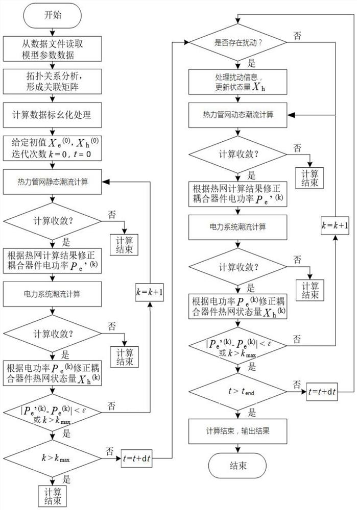
[0084] The invention provides a dynamic power flow analysis method for a multi-energy complementary integrated energy system, which realizes multi-energy coupling through the dynamic power flow calculation of a multi-energy coupling system constructed by non-electric systems such as heat, gas, and cooling, and an electric power system Systematic network analysis. Specifically include the following steps:

[0085] Step 1: Construct a quasi-steady-state model of a non-electrical system

[0086] For ease of description, the embodiment of the dynamic power flow analysis method of the present invention only uses the heating network as an example to describe the quasi-steady model of the non-electrical system provided by the present invention. Non-electrical systems such as gas and cooling networks are similar in structure to the heating network. The non...


PUM


Abstract

The invention provides a dynamic load flow analysis method and a dynamic load flow analysis system for a multi-energy complementary comprehensive energy system. A network analysis on a multi-energy coupling system is carried out by constructing a dynamic load flow model of the multi-energy complementary comprehensive energy system and adopting a mixed solution algorithm, the analysis and calculation of the system level can be effectively supported, and the state change factors in the time domain of the comprehensive energy system are considered. Dynamic load flow rolling calculation based on the time domain is carried out, and the calculation accuracy is improved.

Description

technical field [0001] The invention belongs to the field of energy Internet, and relates to a dynamic power flow analysis method and a dynamic power flow analysis system for a multi-energy complementary comprehensive energy system. Background technique [0002] In recent years, the third industrial revolution characterized by energy Internet has been gaining momentum. The characteristic of the Energy Internet is to use the power grid as the backbone and platform to couple and complement various forms of energy. The network analysis of multi-energy coupling systems is one of the important research contents in the field of Energy Internet. It is the calculation basis and basis for system planning, operation regulation, and energy transactions. Here, not only the energy of the energy supply side and the energy consumption side of the system must be considered. To transform complementarities, the network balance of the multi-energy system should be considered. At present, in ...

Claims


Application Information

Patent Timeline
Patent Type & Authority Patents(China)
IPC IPC(8): H02J3/06
CPCH02J3/06H02J2203/20
Inventor 孙宏斌夏天郭庆来
Owner TSINGHUA UNIV
Learn More