[0023] The technical solutions in the embodiments of the present invention will be clearly and completely described below in conjunction with the accompanying drawings in the embodiments of the present invention. Obviously, the described embodiments are only a part of the embodiments of the present invention, rather than all the embodiments. Based on the embodiments of the present invention, all other embodiments obtained by those of ordinary skill in the art without creative work shall fall within the protection scope of the present invention.
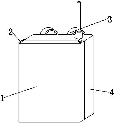
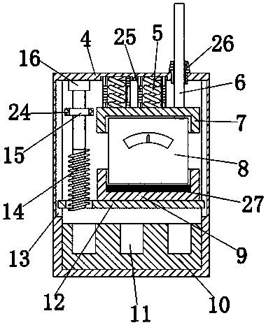
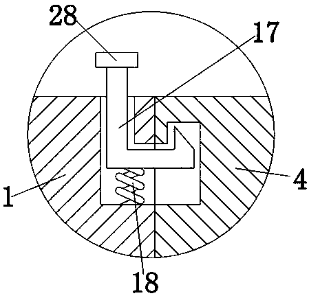
[0024] See Figure 1-4 , The present invention provides a technical solution: a portable backpack-type wireless communication device, which is convenient for users to carry the radio for use in any occasion, including a box body 4 and a strap 3, and the left and right ends of the box body 4 are installed There is a strap 3, and the user can carry the strap 3 on the shoulder. The front of the box 4 is equipped with a box door 1. The box door 1 is connected to the box 4 through a hinge 2, and the box door 1 can be carried around the hinge 2. Rotate to open the box 4, the inner right top of the box 4 is provided with a gland 7, which is connected to the box 4 by a first compression spring 5. The elastic coefficient of the first compression spring 5 is 10N/CM , The outer wall of the first compression spring 5 is sleeved with a silicone sleeve 25, which is used to protect the first compression spring 5 and prevent the first compression spring 5 from being corroded and damaged by humid gas. The inner bottom of the gland 7 is provided with a radio station 8 , The radio station 8 is connected to the gland 7 by overlap, and under the pressure of the first compression spring 5, the gland 7 is pushed down to fix the radio station 8 inside the first base 9 for fixation. The top right side of the radio station 8 is installed with an antenna 6. The antenna 6 penetrates the gland 7 and the box body 4. When the radio 8 is placed inside the first base 9, the antenna 6 is extended out of the gland 7 and the box body 4, and the bottom end of the outer wall of the antenna 6 is sleeved with a rubber head 26. The rubber head 26 is connected to the box 1. The rubber head 26 can prevent the antenna 6 from being worn and damaged by the hole on the right side of the inner top of the box 4, affecting the normal operation of the radio station 8. The bottom end of the radio station 8 is provided with a first base 9. A base 9 is overlapped and connected to the radio station 8. The first base 9 is used to install and fix the radio station 8. The inner bottom of the first base 9 is equipped with a sponge pad 27 which is overlapped and connected to the radio station 8. The sponge pad 27 can make The radio station 8 and the first base 9 fit together better, and can also serve as a buffer and shock absorption function to prevent the radio station 8 from being damaged by severe impact. The bottom end of the first base 9 is equipped with a bottom plate 12, and the box body There are slide grooves 13 on the top left and right sides of the inside of 4, the bottom plate 12 is connected to the slide groove 13 by overlapping, the bottom plate 12 can slide up and down inside the slide groove 13, and the top of the box 4 is provided with lead screws 14 on the left and right. The screw 14 penetrates the bottom plate 12, and the screw 14 is meshed and connected with the bottom plate 12. The rotation of the screw 14 can drive the bottom plate 12 to move up and down. The screw 14 is connected to the box 4 through the bearing 16, and the screw 14 can wrap around the bearing 16 in the box. 4, the top of the outer wall of the screw 14 is sleeved with a runner 15. The user holds the runner 15 by hand and rotates it, which can drive the screw 14 to rotate. The outer wall of the runner 15 is provided with a grinding wheel. The pattern 24 and the grind pattern 24 can increase the friction, which is convenient for the user to hold the wheel 15 and rotate it. The inner bottom end of the box body 4 is equipped with a second base 10, and the inside of the second base 10 is provided with a card. Slot 11, insert the spare battery into the card slot 11 inside the second base 10 for backup. It can be replaced after the radio 8 is out of power to increase the endurance of the radio 8. A hook 17, a button 28 is installed on the top of the first hook 17, the first hook 17 passes through the box door 1 and is connected to the box body 4 by overlap, the first hook 17 passes The second compression spring 18 is connected to the box door 1, and the box door 1 is rotated around the hinge 2 back to its original position, and the first hook 17 is pushed up to the slot inside the box body 4 under the pressure of the second compression spring 18 For fixing, the elastic coefficient of the second compression spring 18 is 10N/CM, a baffle 19 is installed on the front of the strap 3, a cloth strip 20 is installed on the right side of the baffle 19, and a block 21 is installed in the middle of the front of the box body 4. The inside of the block 21 is provided with a second hook 22. The second hook 22 is connected to the block 21 by overlap. The second hook 22 is an elastic element that can automatically return to its original shape after bending. The second hook 22 and the card The blocks 21 are connected to the cloth strip 20 by the frame 23. After the user carries the strap 3 on his shoulders, he holds the frames 23 on the left and right sides with his hands, and inserts the second hook 22 into the block 21 to make The hook 22 is clamped and fixed at the openings on the upper and lower sides of the inner block 21, and the cloth strips 20 on the left and right sides are pulled at the same time, so that the cloth strip 20 drives the baffle 19 to move in the middle to prevent the strap 3 from falling off. The outer wall of the frame 23 A rubber ring 29 is sleeved, and the rubber ring 29 enables the user to better hold the frame 23 and facilitate the user to hold the frame 23 by hand.
[0025] Before use, the user presses down the first hook 17 by hand. The first hook 17 moves down to separate from the slot inside the box 4, and the box door 1 is rotated around the hinge 2 to make the box body 4 is opened, the user holds the runner 15 with his hand and rotates it. The rotation of the runner 15 drives the screw 14 to rotate around the bearing 16 inside the box 4, and the rotation of the screw 4 drives the bottom plate 12 along the sliding groove 13 Slide down, place the radio 8 inside the first base 9, make the antenna 6 extend out of the gland 7 and the box 4, rotate the runner 15, so that the screw 14 drives the bottom plate 12 to move upward, and the bottom plate 12 passes through the bottom plate. A base 9 drives the radio station 8 to move upwards. Under the pressure of the first compression spring 5, push the gland 7 downwards to fix the radio station 8 inside the first base 9 for fixation, and insert the spare battery into the second base 10 The first hook 17 is pushed up to move up to the slot inside the box body 4 for fixing under the pressure of the second compression spring 18 by rotating the box door 1 around the hinge 2 back to its original position. The user carries the harness 3 on his shoulders.
[0026] In the description of the present invention, it should be understood that the terms "coaxial", "bottom", "one end", "top", "middle", "other end", "upper", "one side", "top" "," "in", "front", "center", "both ends", etc. indicate the orientation or positional relationship based on the orientation or positional relationship shown in the drawings, and are only for the convenience of describing the present invention and simplifying the description. It does not indicate or imply that the pointed device or element must have a specific orientation, be constructed and operated in a specific orientation, and therefore cannot be understood as a limitation of the present invention.
[0027] In the present invention, the terms "installation", "setting", "connection", "fixing", "spinning" and other terms should be understood in a broad sense, unless otherwise clearly defined and defined. For example, they can be fixed connection or It can be detachably connected or integrated; it can be mechanically connected or electrically connected; it can be directly connected or indirectly connected through an intermediate medium, and it can be the internal communication of two components or the interaction relationship between two components Unless specifically defined otherwise, those of ordinary skill in the art can understand the specific meanings of the above terms in the present invention according to specific circumstances.
[0028] Although the embodiments of the present invention have been shown and described, those of ordinary skill in the art can understand that various changes, modifications, and substitutions can be made to these embodiments without departing from the principle and spirit of the present invention. And variations, the scope of the present invention is defined by the appended claims and their equivalents.