Magnetic suction impurity removal device

A magnetic suction and magnetic sheet technology, applied in the direction of magnetic separation, solid separation, chemical instruments and methods, etc., can solve the problems of reducing the service life of waste gas treatment equipment, and achieve the effect of easy cleaning and prolonging the service life

Pending Publication Date: 2018-04-24
浙江搏易环保科技有限公司
View PDF0 Cites 0 Cited by
  • Summary
  • Abstract
  • Description
  • Claims
  • Application Information

AI Technical Summary

Problems solved by technology

[0003] However, in the actual production waste gas will always be mixed with iron filings or particles that can be absorbed by magnetic parts, and the gas with particles will enter the

Method used


Image

  • Magnetic suction impurity removal device
  • Magnetic suction impurity removal device
  • Magnetic suction impurity removal device

Examples


Embodiment Construction

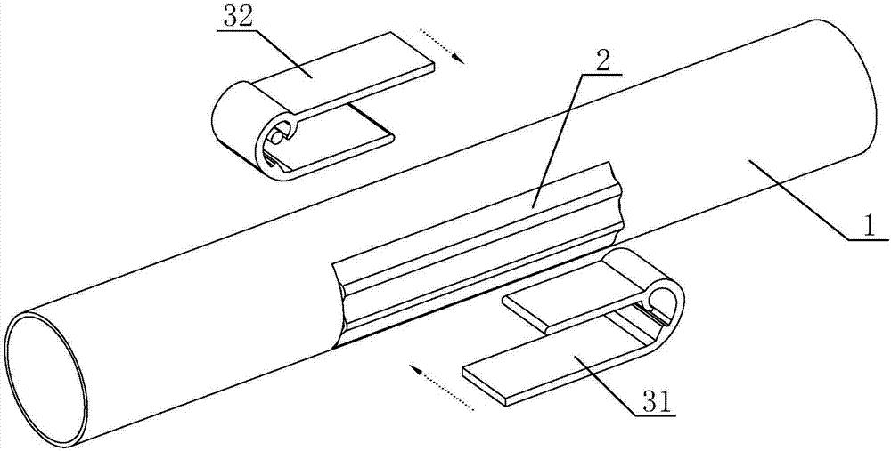
[0022] The present invention will be further described below in conjunction with the accompanying drawings.

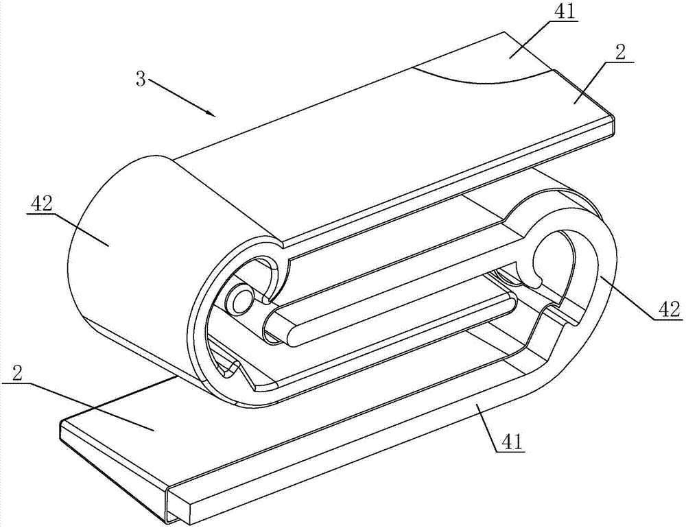
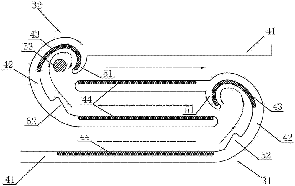
[0023] Such as figure 1 In the magnetic suction impurity removal device shown, the tube body 1 is provided with an air inlet for gas entering and a gas outlet for gas flowing out of the tube body 1, and the tube body 1 is provided with openings symmetrically left and right, and the opening is covered with a pressure film 2 , the pressure film 2 completely covers the two openings to ensure the airtightness of the inside of the tube body 1 except for the inlet and the gas outlet, and the pressure film 2 and the tube body 1 form a completely sealed gas channel. The magnetic suction impurity removal device is also provided with a voltage plate 3, and the voltage plate 3 is provided with a magnetic sheet for absorbing particles in the gas. The voltage plate 3 is divided into two plates, a lower pressing plate 31 and an upper pressing plate 32 . The lower pressing plate 31...


PUM


Abstract

The invention discloses a magnetic suction impurity removal device, which comprises a pipe body provided with an air inlet and an air outlet, and a voltage plate. The pipe body is provided with symmetrical openings left and right, and the opening is covered with a pressure film to prevent gas leakage in the pipe body. , the pressure film and the tube body form a completely sealed gas channel, and the voltage plate is equipped with a magnetic sheet for adsorbing particles in the gas; the voltage plate includes an upper pressure plate and a lower pressure plate, both of which are in a "U" shape, and the upper pressure plate Opposite to the "U"-shaped opening of the lower pressing plate, the straight plates of the upper pressing plate and the lower pressing plate are intersected to form an "S"-shaped air flow channel for gas flow. The invention can separate the iron filings in the gas or the particles that can be absorbed by the magnetic parts from the gas before the gas enters the micro-optic co-resonance waste gas treatment device, so that the waste gas entering the waste gas treatment equipment does not contain particulate matter, and along the length of the equipment service life.

Description

technical field [0001] The invention relates to the technical field of impurity removal devices, in particular to a magnetic suction impurity removal device. Background technique [0002] The low-light resonance waste gas treatment equipment is mainly used for the treatment of various industrial spraying, printing, printing, silk screen volatile organic waste gases, and the deodorization and purification treatment of various malodorous gases. Deodorization and sterilization of organic waste gas in various factories, wastewater treatment stations, hospitals, garbage transfer stations and other places. [0003] However, in the actual production waste gas will always be mixed with iron filings or particles that can be absorbed by magnetic parts, and the gas with particles will enter the waste gas treatment device for treatment, and will accumulate in the treatment device after a long time. Parts are affected, reducing the service life of exhaust gas treatment equipment. Cont...

Claims


Application Information

Patent Timeline
IPC IPC(8): B03C1/02
CPCB03C1/02B03C2201/18
Inventor 贾建洪周士晖吕杭杰陶嘉贵李非里
Owner 浙江搏易环保科技有限公司
Why Eureka
Try Eureka