

High-efficiency cleaning device
A cleaning device and high-efficiency technology, applied in cleaning methods and appliances, cleaning methods using gas flow, transportation and packaging, etc., can solve the problems of debris splashing, negative pressure pipeline adsorption and cleaning effect, etc., to facilitate collection and processing , improve the cleaning effect, improve the effect of the effect
- Summary
- Abstract
- Description
- Claims
- Application Information
AI Technical Summary
Problems solved by technology
Method used
Image

Examples
Embodiment Construction
[0031] The present invention will be further described below in conjunction with the embodiments, and the described embodiments are only a part of the embodiments of the present invention, not all of them. Based on the embodiments of the present invention, other used embodiments obtained by persons of ordinary skill in the art without creative efforts all belong to the protection scope of the present invention.
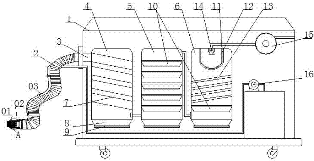
[0032]In conjunction with the accompanying drawings, the high-efficiency cleaning device of the present invention includes a body 1. As a preferred mode of the present invention, the lower end of the body 1 is provided with universal wheels for easy movement. A negative pressure fan 15 is installed on the body 1, so that The body 1 is provided with a negative pressure chamber, the negative pressure port of the negative pressure fan 15 communicates with the negative pressure chamber, and the negative pressure chamber is also connected with a negative pressure channel 3,...
PUM
 Abstract
Description
Claims
Application Information