Hand riveter with integrated rivet-feeding and stapling mechanism
A riveting gun and nail feeding technology, applied in the field of riveting guns, can solve problems such as increased failure rate and unsafety, achieve the effect of reducing the number of parts, improving safety performance and quality, and facilitating promotion
- Summary
- Abstract
- Description
- Claims
- Application Information
AI Technical Summary
Problems solved by technology
Method used
Image
Examples
Embodiment 1
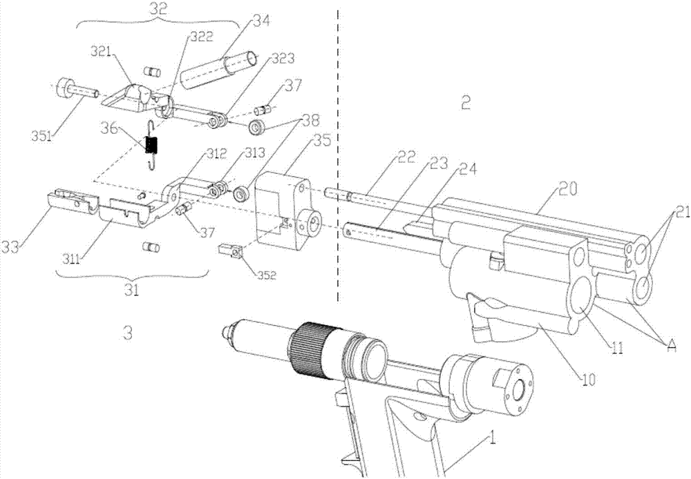
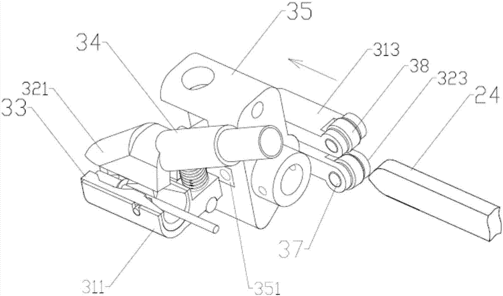
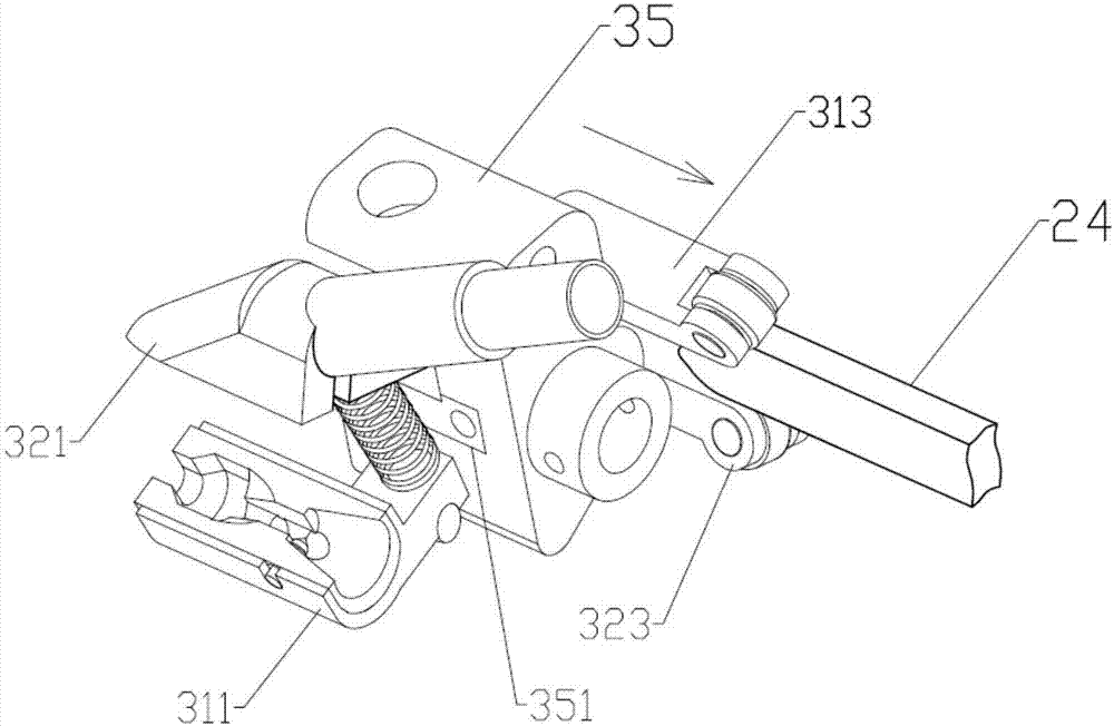
[0022] Such as Figure 1 to Figure 3 As shown, the present invention is a riveting gun with an integrated nail feeding and fixing mechanism, which is composed of a riveting gun body 1, a driving mechanism 2 and a nailing mechanism 3, wherein the respective cylinders of the riveting gun body 1 and the driving mechanism 2 are The collection forms an integrated cylinder A. In the present invention, the integrated cylinder A can be processed into one body by two methods of machining or mold forming. The rivet gun body 1 is a prior art, and its specific structure will not be repeated here. The integrated cylinder A is functionally divided into two parts. They are respectively: the cylinder body 10 belonging to the riveting gun body 1, which includes the riveting gun cylinder 11, and the cylinder body 10 is installed in cooperation with the riveting gun body 1; the cylinder body 20 part belonging to the driving mechanism 2.
[0023] In this embodiment, the integrated cylinder A i...
Embodiment 2
[0031] In this embodiment, the integrated cylinder body A includes: a blind riveting cylinder 10 , an air cylinder 21 and a chute 25 . Wherein, the driving mechanism 2 adopts a cylinder 21 and a push rod 26 structure of a chute 25, that is: the cylinder body 20 is provided with a cylinder 21, a piston rod 23, a strut 24, a chute 25 and a slide rod 26 constitute. In this embodiment, the piston rod 23 of the cylinder 21 and the sliding rod 25 of the chute 25 jointly drive the staple mechanism to move back and forth. Wherein the piston rod 23 of the cylinder 21 is used to drive the staple mechanism 3 to move back and forth; the push rod 26 moving in cooperation with the chute 25 plays a stabilizing effect on the staple mechanism. The piston rod 23 is used to push the staple mechanism 3 to move back and forth, and the push rod plays a balancing role. The working principle of this implementation is the same as that of Embodiment 1, see the accompanying drawings Figure 4 and 5 ...
PUM
 Abstract
Description
Claims
Application Information
 - R&D
- Intellectual Property
- Life Sciences
- Materials
- Tech Scout
- Unparalleled Data Quality
- Higher Quality Content
- 60% Fewer Hallucinations
Browse by: Latest US Patents, China's latest patents, Technical Efficacy Thesaurus, Application Domain, Technology Topic, Popular Technical Reports.
© 2025 PatSnap. All rights reserved.Legal|Privacy policy|Modern Slavery Act Transparency Statement|Sitemap|About US| Contact US: help@patsnap.com


