Printing head spacing adjustment device

A technology for adjusting devices and print heads, which is applied in the direction of power transmission devices, printing, transfer materials, etc., can solve the problems of inability to precisely and accurately adjust the distance between the print head and the printing medium, affecting the accuracy of distance adjustment, and difficult maintenance. To achieve the effect of improving product competitiveness, low cost and easy maintenance

Active Publication Date: 2018-04-24
TECO IMAGE SYST
View PDF16 Cites 2 Cited by
  • Summary
  • Abstract
  • Description
  • Claims
  • Application Information

AI Technical Summary

Problems solved by technology

The print head spacing adjustment device is used to adjust the distance between the print head and the printing medium. The traditional print head spacing adjustment device is usually realized by a linear stroke adjustment mechanism combined with a ball screw and a guide rod. Not only can the mechanism not precisely and accurately adjust the distance between the print head and the printing medium, but it is also expensive, large in size, and difficult to maintain
In addition, another existing technology is to use a linear stroke adjustment mechanism combined with a gear and a rack to achieve the distance adjustment function, but the linear stroke adjustment mechanism combined with a gear and a rack is often unable to bear the stress during use. And wear, and there will also be backlash problems, which will affect the accuracy of spacing adjustment

Method used


Image

  • Printing head spacing adjustment device
  • Printing head spacing adjustment device
  • Printing head spacing adjustment device

Examples


Embodiment Construction

[0076] Some typical embodiments embodying the features and advantages of the present invention will be described in detail in the description in the following paragraphs. It should be understood that the present invention is capable of various changes in different embodiments without departing from the scope of the present invention, and that the description and drawings therein are to be regarded as illustrative in nature, not for the purpose of limit the invention.

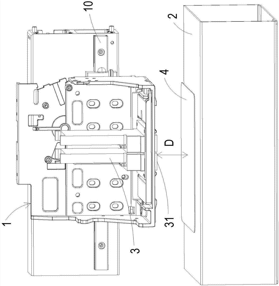
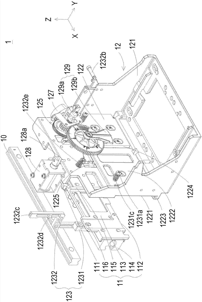
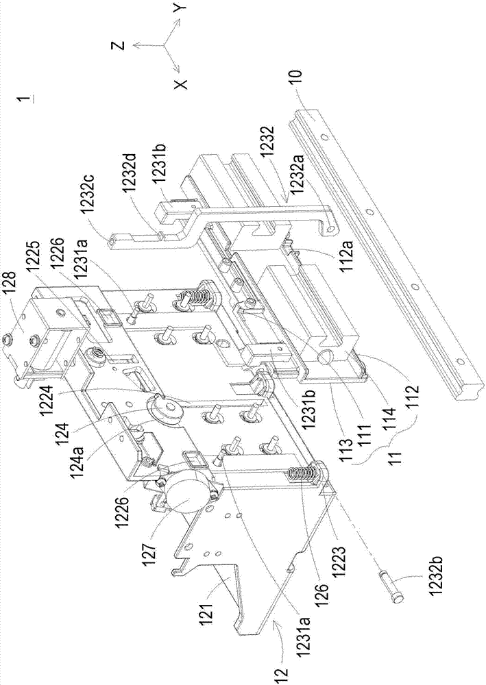
[0077] figure 1 It is a partial structural schematic diagram disclosing the application of the printing head spacing adjustment device of the present invention to an inkjet printer, Figure 2A and Figure 2BIt is a schematic diagram of the disassembled structure of the printing head spacing adjustment device disclosed in the first preferred embodiment of the present invention at different viewing angles, Figure 2C is public Figure 2A The side view of the exploded structure of the print head spacing adjustm...


PUM


Abstract

The invention provides a printing head spacing adjustment device comprising a sliding base and an ink box frame. The sliding base is provided with a top edge, a bottom edge and a first attaching surface. The ink box frame comprises a containing groove, an attaching wall, a clamping set, a variable-radius cam, a driving gear set and an elastic assembly. The clamping set is arranged between the sliding base and the ink box frame and selectively clamps the sliding base and the ink box frame to limit movement of the ink box frame relative to the sliding base. The elastic assembly is arranged at the bottom edges of the ink box frame and the sliding base in a connected mode. The variable-radius cam is arranged on a second attaching surface and provided with a peripheral edge to abut against thetop edge of the sliding base. The driving gear set is arranged on an adjustment and control surface, and the driving gear set and the variable-radius cam are coaxially connected and can rotate synchronously, wherein the driving gear set drives the variable-radius cam to rotate to adjust the height of the ink box frame relative to the sliding base.

Description

technical field [0001] The invention relates to an adjusting device of an ink-jet printer, in particular to a device for adjusting the distance between printing heads of the ink-jet printer. Background technique [0002] Generally, Wide Format Inkjet printers (Wide Format Inkjet printers) used for outputting large images often require the use of different types of printing media. However, different types of printing media have different thickness differences. During printing, the difference in the distance between the printhead of the ink cartridge and the inking surface of the printing medium will directly affect the quality of the printed image output. Therefore, the distance control of the print head relative to the printing medium is very important, and the adjustable precise value must be quite fine. [0003] With the improvement of printing resolution and the development of inkjet ink droplet miniaturization, the precision requirements of the body structure are also ...

Claims


Application Information

Patent Timeline
Patent Type & Authority Applications(China)
IPC IPC(8): B41J25/308
CPCB41J25/3088
Inventor 陈健民
Owner TECO IMAGE SYST
Why Eureka
Try Eureka