Battery box hoisting device

A hoisting device and battery box technology, applied in the direction of transportation and packaging, load hanging components, etc., can solve the problems of high work intensity of workers, difficult alignment of falling points, and easy detachment of steel wire ropes, etc. Significant significance of production practice, to achieve the effect of accurate control

Pending Publication Date: 2018-04-24
WUHAN LISHEN POWER CELL SYST TECH CO LTD
View PDF0 Cites 12 Cited by
  • Summary
  • Abstract
  • Description
  • Claims
  • Application Information

AI Technical Summary

Problems solved by technology

At this time, because the wire rope 11 is flexible, the battery box 10 is likely to shake back and forth, left and right during the hoisting process, and it is easy to touch other battery boxes 10 around, causing damage to the battery box 10. Putting it into the packing carton at the designated location, the drop point is not easy to align; in addition, because the steel wire rope is gathered together at the lifting place of the battery box, the steel wire rope will be tight on the waterproof edge of the battery box cover and move during the hoisting process. It is inevitable to generate friction, thereby easily scratching the paint on the waterproof edge of the battery box cover; in addition, before the steel wire rope 11 is lifted and tightened to the battery box, artificial external force is required to tighten the battery box, otherwise the steel wire rope is easy to come out of the battery box lifting lugs, therefore, the work intensity of the workers is high, and the overall efficiency of lifting the battery box is reduced
[0003] However, there is no technology at present, which can ensure the stable and reliable hoisting of the battery box, so that the battery box will not shake back and forth, left and right during the hoisting process, and realize accurate control of the hoisting operation of the battery box

Method used


Image

  • Battery box hoisting device
  • Battery box hoisting device
  • Battery box hoisting device

Examples


Embodiment Construction

[0029] In order to enable those skilled in the art to better understand the solution of the present invention, the present invention will be further described in detail below in conjunction with the accompanying drawings and embodiments.

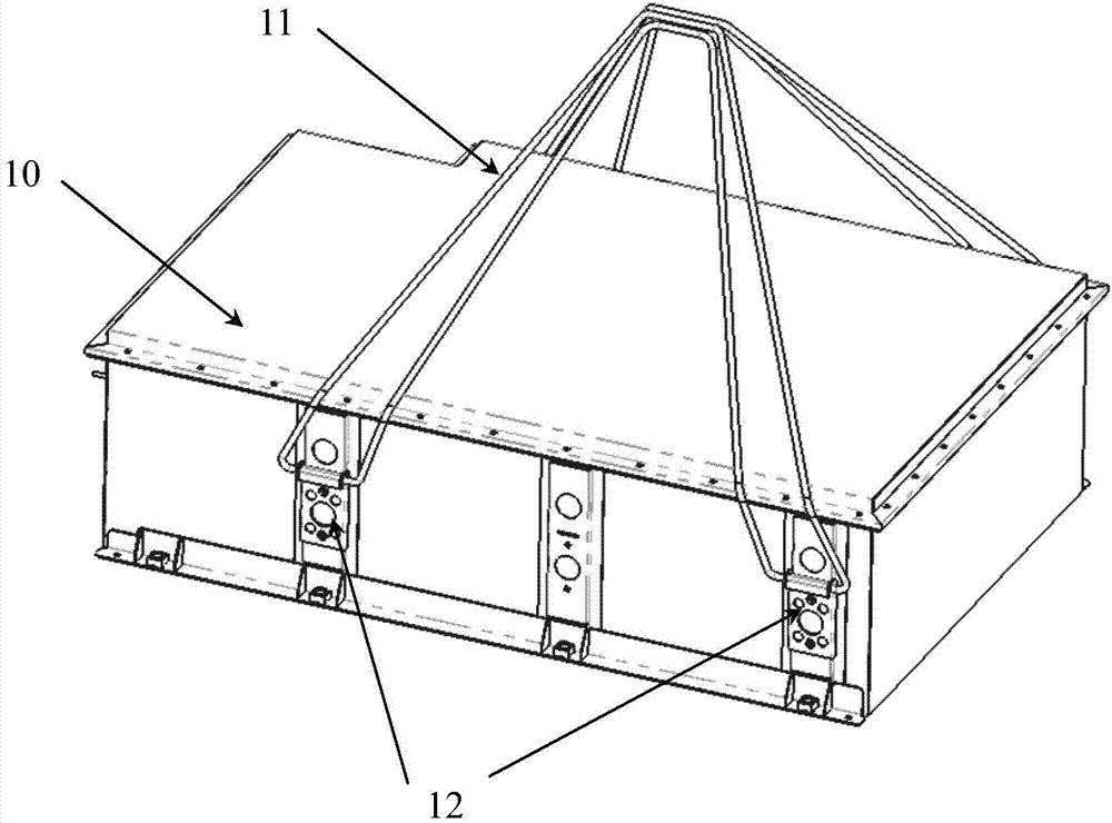
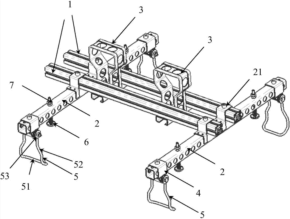
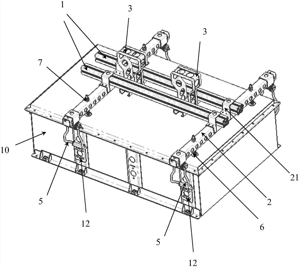
[0030] see Figure 1 to Figure 4 , the present invention provides a battery box hoisting device, comprising two longitudinal beams 2 parallel to each other and distributed longitudinally at intervals, and the tops of the two longitudinal beams 2 are provided with two crossbeams 1 parallel to each other and distributed laterally at intervals;

[0031] The two beams 1 are provided with two hoisting frames 3, and the two hoisting frames 3 are used to be connected with an external hoisting device (such as a fork of a forklift);

[0032] A sliding ring 4 is provided at the front and rear ends of each longitudinal beam 2, and the lower part of each sliding ring 4 is hinged with a hook 5;

[0033] The four hooks 5 are correspondingly connected to ...


PUM


Abstract

The invention discloses a battery box hoisting device, which comprises two longitudinal beams (2) parallel to each other and longitudinally spaced apart, and the tops of the two longitudinal beams (2) are provided with two mutually parallel transversely spaced transverse beams (1); the two beams (1) are provided with two lifting brackets (3); the front and rear ends of each longitudinal beam (2) are distributed with a sliding ring (4), each of the The lower part of the sliding ring (4) is hinged with a hook (5); the four hooks (5) correspond to the four lifting lugs (12) installed on the front and rear side walls of the battery box (10) to be hoisted connect. The invention can ensure the stable and reliable hoisting of the battery box, so that the battery box will not shake back and forth, left and right during the hoisting process, and realize accurate control of the hoisting operation of the battery box, which is conducive to wide popularization and application, and can form an industrial The large-scale production has great practical significance.

Description

technical field [0001] The invention relates to the technical field of hoisting devices, in particular to a hoisting device for a battery box. Background technique [0002] Currently, see figure 1 , during the hoisting and packaging process of the existing battery box 10, the steel wire rope 11 needs to be passed on the lifting lugs 12 fixed on the front and rear side walls of the battery box 10, and then hoisted. At this time, because the wire rope 11 is flexible, the battery box 10 is likely to shake back and forth, left and right during the hoisting process, and it is easy to touch other battery boxes 10 around, causing damage to the battery box 10. Putting it into the packing carton at the designated location, the drop point is not easy to align; in addition, because the steel wire rope is gathered together at the lifting place of the battery box, the steel wire rope will be tight on the waterproof edge of the battery box cover and move during the hoisting process. It ...

Claims


Application Information

Patent Timeline
Patent Type & Authority Applications(China)
IPC IPC(8): B66C1/28B66C13/06
CPCB66C1/28B66C13/06
Inventor 汪涛张琛李汉林
Owner WUHAN LISHEN POWER CELL SYST TECH CO LTD
Why Eureka
Try Eureka