Fireproof structure of pipe joints in immersed tunnels

A technology for fireproof structures and immersed tunnels, which is applied to underwater structures, infrastructure engineering, buildings, etc., can solve problems such as the inability to meet the displacement requirements, the inability to meet the fire protection requirements due to fire prevention, and the impact on the service life of waterproof belt components. Achieve the effect of increasing the service life and improving the fire resistance

Active Publication Date: 2019-07-19
CHINA CONSTR ENG HONG KONG
View PDF4 Cites 0 Cited by
  • Summary
  • Abstract
  • Description
  • Claims
  • Application Information

AI Technical Summary

Problems solved by technology

If a fire breaks out in the pipeline, the fire will inevitably affect the service life of the waterproof belt assembly. Therefore, the current common practice is to install a fireproof board to meet the fireproof requirements of the waterproof belt assembly. However, the existing fireproof board has the following problems: Only fire-proof boards are installed. After testing, the existing fire-proof design meets the fire-proof requirements of two hours, that is, a fire in the pipeline will not affect the waterproof belt components within two hours, and the two-hour fire-proof time limit can no longer achieve effective fire protection. need
At the same time, the two adjacent pipes require longitudinal displacement, and the existing joint structure only has one fireproof board, which cannot meet the displacement requirements

Method used


Image

  • Fireproof structure of pipe joints in immersed tunnels
  • Fireproof structure of pipe joints in immersed tunnels
  • Fireproof structure of pipe joints in immersed tunnels

Examples


Embodiment Construction

[0024] The following will clearly and completely describe the technical solutions in the embodiments of the present invention with reference to the accompanying drawings in the embodiments of the present invention. Obviously, the described embodiments are only part of the embodiments of the present invention, not all of them. Based on the embodiments of the present invention, all other embodiments obtained by persons of ordinary skill in the art without creative efforts fall within the protection scope of the present invention.

[0025] It should be noted that all directional indications (such as up, down, left, right, front, back...) in the embodiments of the present invention are only used to explain the relationship between the components in a certain posture (as shown in the accompanying drawings). Relative positional relationship, movement conditions, etc., if the specific posture changes, the directional indication will also change accordingly.

[0026] In the present in...


PUM


Abstract

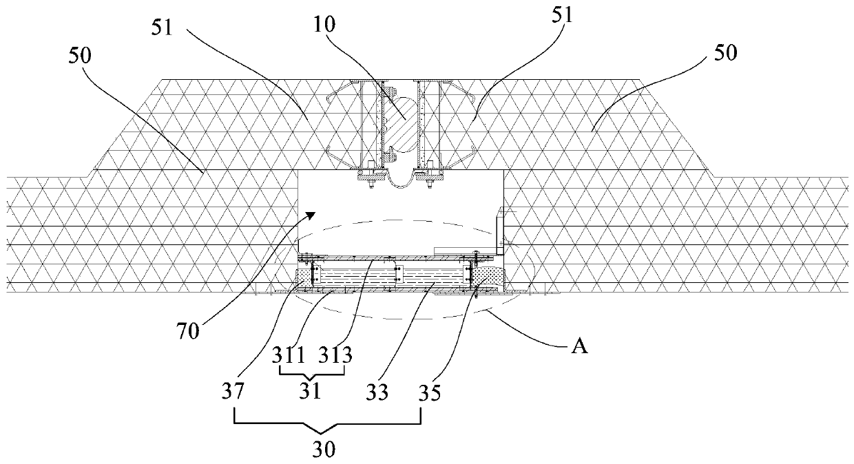
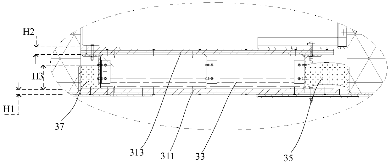
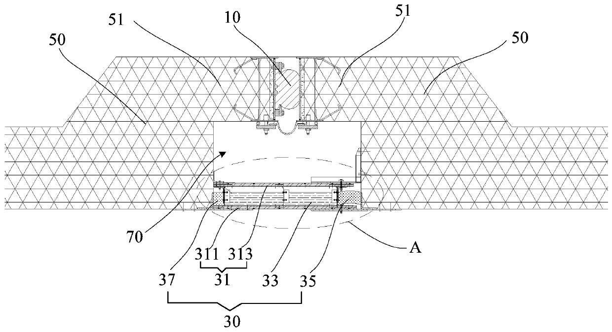
A fire protection structure applied to a segment joint of an immersed tunnel comprises a watertight band assembly (10) and a fire protection assembly (30) that are connected between two adjacent tunnel segments (50) and spaced apart from each other. The fire protection assembly (30) is positioned at an inner side of the watertight band assembly (10). The fire protection assembly (30) comprises: a protection plate assembly (31), comprising a first fire protection plate (311) and a second fire protection plate (313) that are spaced apart from each other and a heat insulation member (33) fixed therebetween, wherein one end of each of the first fire protection plate (311) and the second fire protection plate (313) is connected to one tunnel segment (50), and the other end thereof is movably connected to the other tunnel segment (50); and a flexible fire protection band (35), positioned between the first fire protection plate (311) and the second fire protection plate (313), wherein one end of the flexible fire protection band (35) is connected to the heat insulation member (33), and the other end thereof is connected to the tunnel segment (50).

Description

technical field [0001] The invention relates to the technical field of immersed tube tunnels, in particular to a fireproof structure for pipe joint joints of immersed tube tunnels. Background technique [0002] In the immersed tube construction tunnel, the connection between two adjacent pipelines needs to be connected with a waterproof belt assembly, such as a rubber waterstop strip, to prevent external moisture from penetrating into the pipeline through the connection. The waterproof belt assembly In addition to meeting the longitudinal expansion and contraction displacement between tunnel pipe sections, the fire protection requirements must be met within the design period (for example, 120 years), so as to ensure the overall fire performance of the tunnel structure. If a fire breaks out in the pipeline, the fire will inevitably affect the service life of the waterproof belt assembly. Therefore, the current common practice is to install a fireproof board to meet the firepr...

Claims


Application Information

Patent Timeline
Patent Type & Authority Patents(China)
IPC IPC(8): E02D29/073E02D29/16E02D31/00
CPCE02D29/073E02D29/16E02D31/00
Inventor 潘树杰何军陈长卿佟安岐
Owner CHINA CONSTR ENG HONG KONG
Why Eureka
Try Eureka