Engine brake executing mechanism

An engine braking and actuator technology, applied in engine control, engine components, machines/engines, etc., can solve the problems of slow braking clearance adjustment, uncontrollable braking stroke, complex structure, etc. Simple structure, flexible control effect

Active Publication Date: 2018-04-24
DONGFENG COMML VEHICLE CO LTD
View PDF8 Cites 3 Cited by
  • Summary
  • Abstract
  • Description
  • Claims
  • Application Information

AI Technical Summary

Problems solved by technology

[0004] The purpose of the present invention is to overcome the defects and problems of complex structure, slow brake gap adjustment speed and uncontrollable brake stroke existing in the prior art, and provide a simple structure, fast brake gap adjustment speed, and controllable brake stroke. engine brake actuator

Method used


Image

  • Engine brake executing mechanism
  • Engine brake executing mechanism
  • Engine brake executing mechanism

Examples


Embodiment

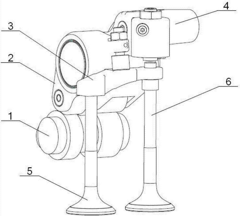
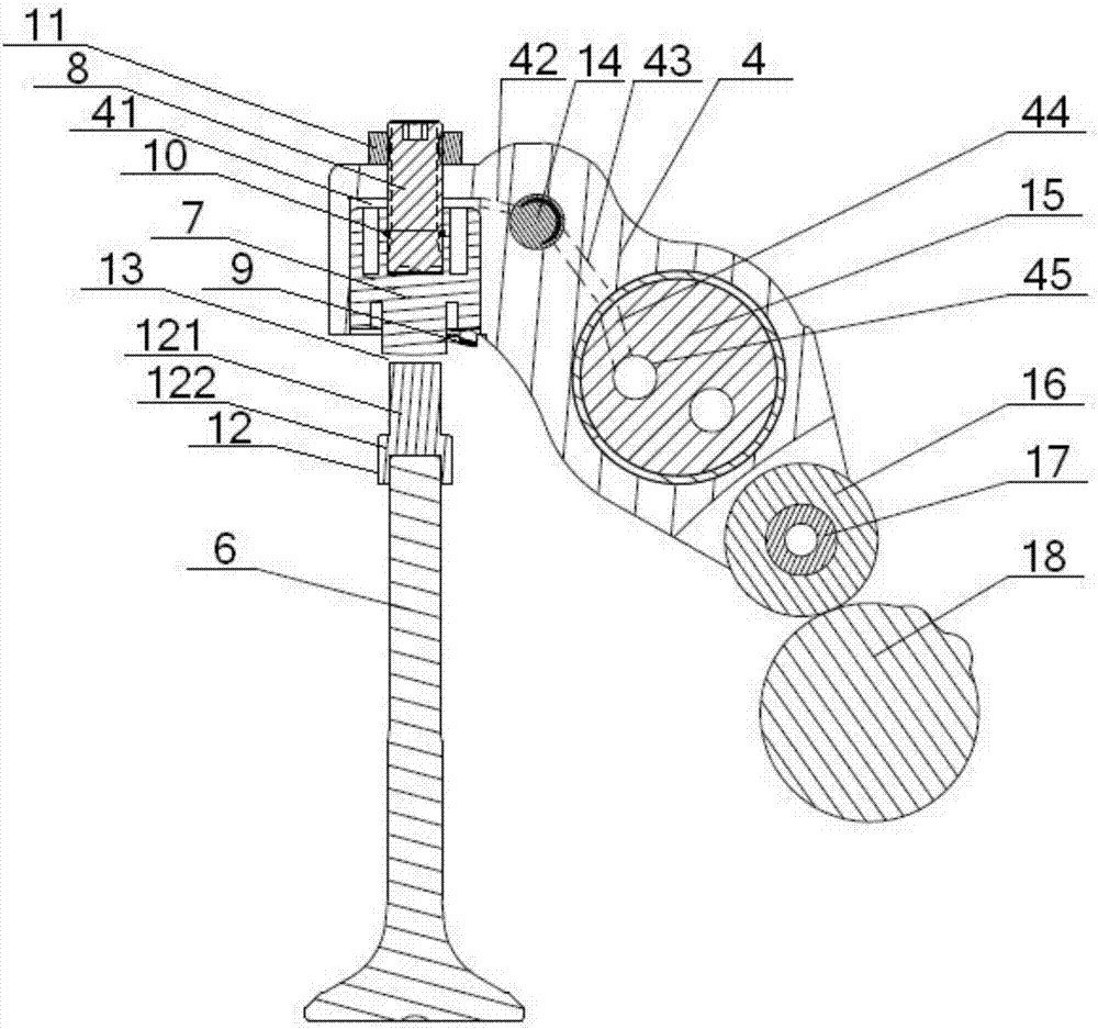
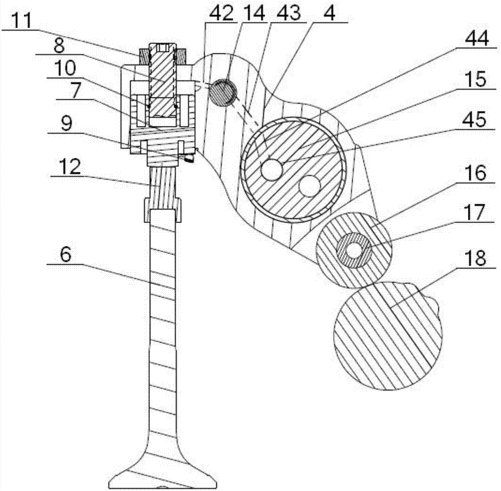
[0035] see Figure 1 to Figure 4 , an engine brake actuator, including the brake inner chamber 41 of the rocker arm 4 and the brake actuator piston 7 and the adjusting bolt 8 arranged inside it, the brake inner chamber 41 and the brake oil in the rocker arm 4 The road 42 communicates, and the bottom of the brake actuator piston 7 is provided with a valve yoke 3, and the valve yoke 3 is provided with a No. 1 valve 5 and a No. 2 valve 6; the engine brake actuator also includes a brake piston spring 9 1. Circlip 10, one end of the adjustment bolt 8 passes through the brake inner cavity 41 and the rocker arm 4 in turn and is connected with the lock nut 11 outside the rocker arm 4, and the outer wall of the other end of the adjustment bolt 8 is provided with a No. 2 card slot 81, the inner wall of the end of the brake actuator piston 7 close to the adjustment bolt 8 is provided with a No. 2 card slot, and the bottom of the brake actuator piston 7 is provided with a brake piston at ...


PUM


Abstract

The invention discloses an engine brake executing mechanism. The mechanism comprises a brake inner cavity, a brake executing piston, an adjusting bolt, a brake piston spring and a clamp spring, wherein the brake executing piston, the adjusting bolt, the brake piston spring and the clamp spring arranged inside the brake inner cavity; one end of the adjusting bolt is connected with a locking nut, afirst clamping groove is formed in the outer wall of the other end of the adjusting bolt, a second clamping groove is formed in the inner wall of the brake executing piston, and the brake piston spring is arranged at the bottom of the brake executing piston; the inner side part of the clamp spring is located in the first clamping groove, and the outer side part of the clamp spring is fixed in thesecond clamping groove; and the brake inner cavity communicates with a brake oil way, one end of an air valve yoke arranged below the brake executing piston is connected with a first air valve, the other end of the air valve yoke sleeves a brake push rod, one end of the brake push rod is connected with a second air valve, and a valve clearance is formed between the other end of the brake push rodand the brake executing piston located right above the brake push rod. According to the mechanism, the structure is simple, the brake clearance adjusting speed is high, the brake stroke is controllable, the air valves are flexible to control, and the operation is simple and convenient.

Description

technical field [0001] The invention relates to an engine braking control device, which belongs to the technical field of vehicle engine braking, and in particular to an engine braking actuator, which is mainly suitable for simplifying the structure, increasing the speed of adjusting the braking gap, and realizing the controllable braking stroke. Background technique [0002] The oil circuit control mechanism and actuator of the brake rocker arm are relatively mature with Jacob's special rocker arm system and VOLVO's VEB system. The brake oil circuit control mechanism is basically based on the one-way valve structure under braking conditions. Realize the formation and locking of the high-pressure oil chamber under braking conditions; the domestic Youshun brake adopts a simple solenoid valve switch and oil drain control method. Different brake actuators determine the difference of the oil circuit control mechanism. For brake actuators, the general principle is that the oil pr...

Claims


Application Information

Patent Timeline
Patent Type & Authority Applications(China)
IPC IPC(8): F02D13/04F01L13/06F01L1/20F01L1/46
CPCF01L1/20F01L1/46F01L13/06F02D13/04
Inventor 万虎张芳华建杰吴囿霖
Owner DONGFENG COMML VEHICLE CO LTD
Why Eureka
Try Eureka