
A microcomputer-electric-hydraulic servo joint control field rock and soil mechanics test device and method

A technology of geotechnical mechanics and test equipment, which is applied in the direction of using optical equipment, measuring equipment, and applying stable tension/pressure to test the strength of materials. and other problems, to achieve the effect of high-precision large-flow whole-process control, good rock and soil deformation and strength characteristics, reliability and resolution improvement.

Active Publication Date: 2020-04-14
CHANGJIANG RIVER SCI RES INST CHANGJIANG WATER RESOURCES COMMISSION
View PDF7 Cites 0 Cited by
  • Summary
  • Abstract
  • Description
  • Claims
  • Application Information

AI Technical Summary

Problems solved by technology

[0003] To sum up, the problems existing in the existing technology are: ① In order to meet the requirements of large flow and high precision, the working principle of the electro-hydraulic servo control itself determines that the size of the device is large and clumsy, and the cost will naturally increase; ② the existing The gas-liquid loading equipment has not realized servo control, the main reason is that the precision of the gas servo valve at home and abroad is low, and the supporting method is not perfect, so there is no field servo control loading equipment with high precision and large flow; ③In the field environment, servo loading The unloading and data acquisition system and corresponding sensors are greatly affected by temperature and humidity, and its stability and reliability are difficult to achieve satisfactory results; ④ A set of devices in the prior art can only meet the loading and acquisition of a single channel. If two or more loading and unloading channels are required, more than two independent devices need to be configured, which brings problems such as difficulty in synchronization, insufficient flow, and increased cost.

Method used


Image

  • A microcomputer-electric-hydraulic servo joint control field rock and soil mechanics test device and method

Examples


Embodiment Construction

[0022] In order to make the object, technical solution and advantages of the present invention more clear, the present invention will be further described in detail below in conjunction with the examples. It should be understood that the specific embodiments described here are only used to explain the present invention, not to limit the present invention.

[0023] The invention can perform high-precision servo control on the pressure of all on-site rock-soil mechanics test items, and solves the long-standing and difficult problem of intelligentization of on-site rock mechanics tests.

[0024] The application principle of the present invention will be described in detail below in conjunction with the accompanying drawings.

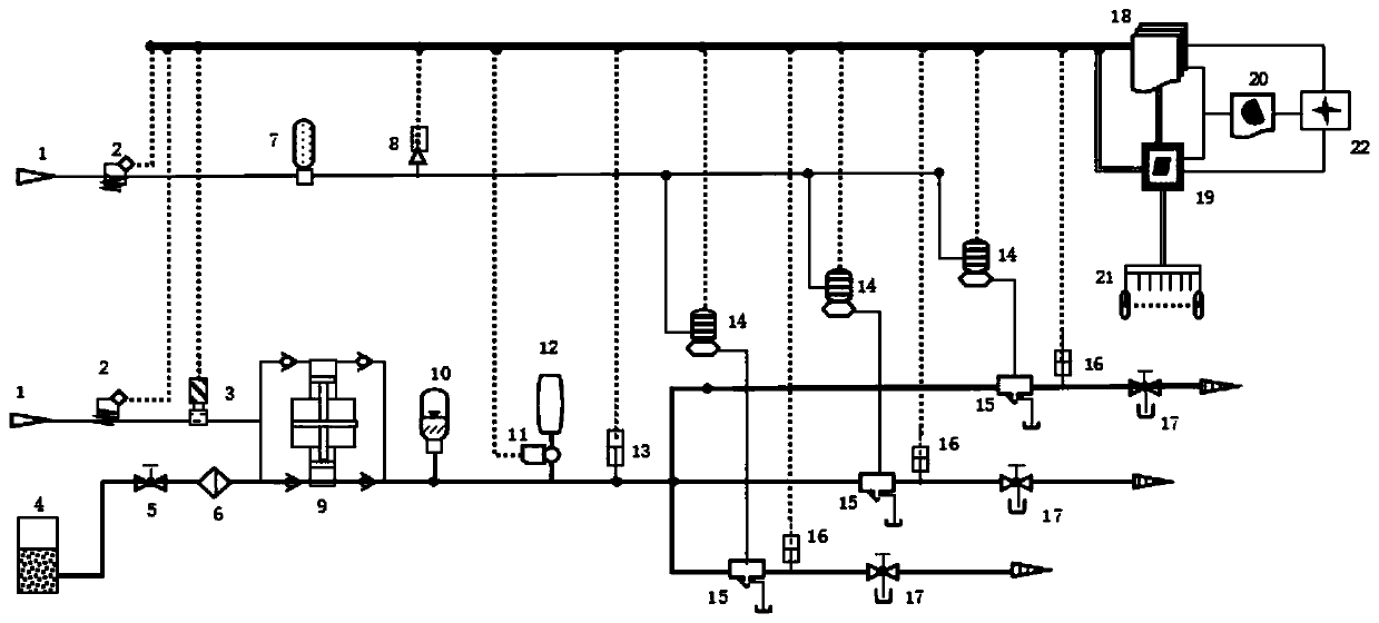
[0025]The field rock-soil mechanics test device and method provided by the embodiment of the present invention include a pneumatic control system, a hydraulic control system, and an electric control system. Pneumatic power is provided by a small air compre...


PUM


Abstract

The invention discloses a microcomputer electricity, gas and liquid servo joint control field rock-soil mechanics experiment device and method. The device comprises a pneumatic control system, a hydraulic system and an electric control system. A small air compressor provides air power, a bidirectional gas-liquid pressurizing pump is used to convert low air pressure into high liquid pressure whichis provided for three electricity, gas and liquid servo valve and a depressurizing valve through pressure stabilizing, and three different pressures are output at the same time under control of a computer and software. Displacement of an experiment object can be collected synchronously, and a stress-strain relation curve can be displayed in real time. Air pressure and air control elements are adopted to realize servo joint control on high liquid pressure, output pressure is high in accuracy and small in fluctuation, and maximum fluctuation range is smaller than + / -20kPa; three different pressures are output at the same time, output flow is large and free of mutual interference, highest output pressure is 60MPa, and one equipment can meet all projects of a field rock-soil mechanics experiment. The device is simple in structure, convenient to operate and capable of well adapting to field harsh environment.

Description

technical field [0001] The invention belongs to the technical field of rock-soil mechanics test equipment, and in particular relates to a field rock-soil mechanics test device and method controlled by microcomputer-electric-hydraulic servo joint control. Background technique [0002] Rock and soil mechanics field tests include compression deformation tests, direct shear tests, bearing capacity tests, uniaxial, biaxial and triaxial tests, and creep tests for corresponding projects. The mechanical parameters of rock and soil are obtained by applying stress to the rock and soil specimen to cause deformation or destruction. At present, the loading and recording of on-site rock and soil mechanics tests mainly use manual loading and manual data recording. Due to the complex field environmental conditions and the large differences in rock and soil mechanics parameters, the applied load and flow must be in a wide range. Therefore, the existing The technology is either difficult to ...

Claims


Application Information

Patent Timeline
Patent Type & Authority Patents(China)
IPC IPC(8): G01N3/12G01B11/16
CPCG01B11/165G01N3/12
Inventor 李维树宋春恩周火明李强袁亚东吴相超刘洋郑升宝郭喜峰乔云强王中豪谭新刘学祥张宜虎谢春光
Owner CHANGJIANG RIVER SCI RES INST CHANGJIANG WATER RESOURCES COMMISSION
Learn More