
Cable joint detection device and method based on X-ray scanning

A technology of optical scanning device and cable joint, which is applied in the direction of fault location and fault detection according to conductor type, can solve the problems of increased probability of failure of cable joint and uneven quality of cable accessories, and achieves easy operation and simple structure , the effect of ensuring safety

Inactive Publication Date: 2018-04-24
STATE GRID SHANDONG ELECTRIC POWER +1
View PDF7 Cites 6 Cited by
  • Summary
  • Abstract
  • Description
  • Claims
  • Application Information

AI Technical Summary

Problems solved by technology

[0003] The cable terminal head and the middle head are important components in the transmission and transformation cables. Due to the differences in the operation mode and conditions of the cable joints, the technical level of the construction personnel is different, and the quality of the cable accessories is uneven, resulting in the probability of failure of the cable joints. greatly increase

Method used


Image

  • Cable joint detection device and method based on X-ray scanning
  • Cable joint detection device and method based on X-ray scanning
  • Cable joint detection device and method based on X-ray scanning

Examples


Embodiment Construction

[0060] In order to clearly illustrate the technical features of this solution, the present invention will be described in detail below through specific implementation modes and in conjunction with the accompanying drawings. The following disclosure provides many different embodiments or examples for implementing different structures of the present invention. To simplify the disclosure of the present invention, components and arrangements of specific examples are described below. Furthermore, the present invention may repeat reference numerals and / or letters in different instances. This repetition is for the purpose of simplicity and clarity and does not in itself indicate a relationship between the various embodiments and / or arrangements discussed. It should be noted that components illustrated in the figures are not necessarily drawn to scale. Descriptions of well-known components and processing techniques and processes are omitted herein to avoid unnecessarily limiting the...


PUM


Abstract

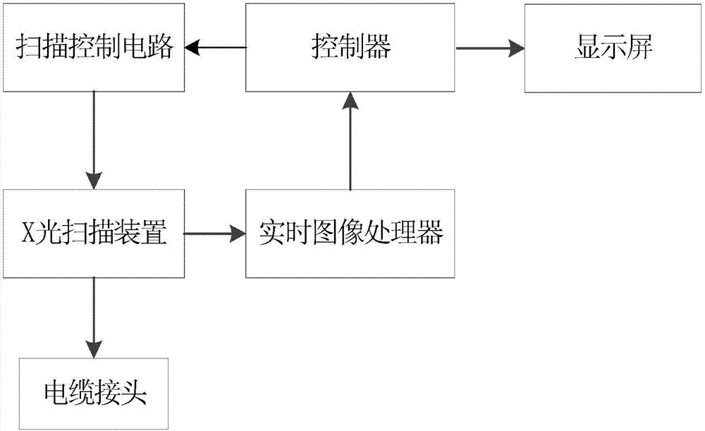
The invention discloses a cable joint detection device and a cable joint detection method based on X-ray scanning. The cable joint detection device comprises an X-ray scanning device, a real-time image processor, a scanning control circuit, a controller and a display screen, wherein the X-ray scanning device is used for performing X-ray scanning on a cable joint; an input end of the real-time image processor is connected with an output end of the X-ray scanning device; an output end of the real-time image processor is connected with the controller, and is used for preprocessing an X-ray imageof the cable joint and transmitting the preprocessed X-ray image of the cable joint to the controller for carrying out cable joint detection processing; an input end of the scanning control circuit isconnected with the controller, an output end thereof is connected with a control end of the X-ray scanning device, and the scanning control circuit is used for controlling the X-ray scanning device;and the display screen is connected with the controller, and is used for outputting a detection result of the cable joint. The cable joint detection device and the cable joint detection method can beused for performing effective detection on the integrity of the cable joint, and reduce the cable failure rate caused by the quality problem of the cable joint.

Description

technical field [0001] The invention relates to the field of cable joint detection, in particular to a cable joint detection device and method based on X-ray scanning. Background technique [0002] The cable is an important part of the power system, and its intact joints and accessories are of great significance to ensure the safe and reliable operation of the power system. Well-designed and well-constructed cable joints have been proved by actual operation to be able to operate for a long time in most cases. [0003] The cable terminal head and the middle head are important components in the transmission and transformation cables. Due to the differences in the operation mode and conditions of the cable joints, the technical level of the construction personnel is different, and the quality of the cable accessories is uneven, resulting in the probability of failure of the cable joints. greatly increase. [0004] Therefore, it is necessary to detect the integrity of the cabl...

Claims


Application Information

Patent Timeline
Patent Type & Authority Applications(China)
IPC IPC(8): G01R31/08
CPCG01R31/083
Inventor 姜涛钱庆林葛少伟刘哲邝涛王家斌侯建峰孟庆瑞刘圣安
Owner STATE GRID SHANDONG ELECTRIC POWER
Learn More