Light emitting device

A technology of transmitting device and transmitting unit, which is applied in the field of optical communication, can solve problems such as laser pollution and energy waste of optical communication equipment, achieve high application value, reduce heat and laser pollution, and reduce energy consumption of equipment

Active Publication Date: 2018-04-24
NEW H3C TECH CO LTD
View PDF4 Cites 2 Cited by
  • Summary
  • Abstract
  • Description
  • Claims
  • Application Information

AI Technical Summary

Problems solved by technology

In this way, not only the energy of optical communication equipment is wasted, additional heat is generated, but also additional laser pollution is caused.

Method used


Image

  • Light emitting device
  • Light emitting device
  • Light emitting device

Examples


Embodiment Construction

[0028] Reference will now be made in detail to the exemplary embodiments, examples of which are illustrated in the accompanying drawings. When the following description refers to the accompanying drawings, the same numerals in different drawings refer to the same or similar elements unless otherwise indicated. The implementations described in the following exemplary embodiments do not represent all implementations consistent with this application. Rather, they are merely examples of apparatuses and methods consistent with aspects of the present application as recited in the appended claims.

[0029] The terminology used in this application is for the purpose of describing particular embodiments only, and is not intended to limit the application. As used in this application and the appended claims, the singular forms "a", "the", and "the" are intended to include the plural forms as well, unless the context clearly dictates otherwise. It should also be understood that the term...


PUM


Abstract

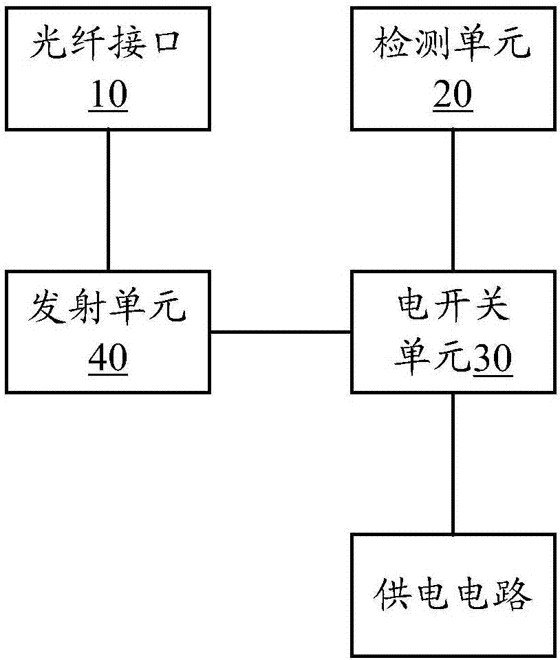
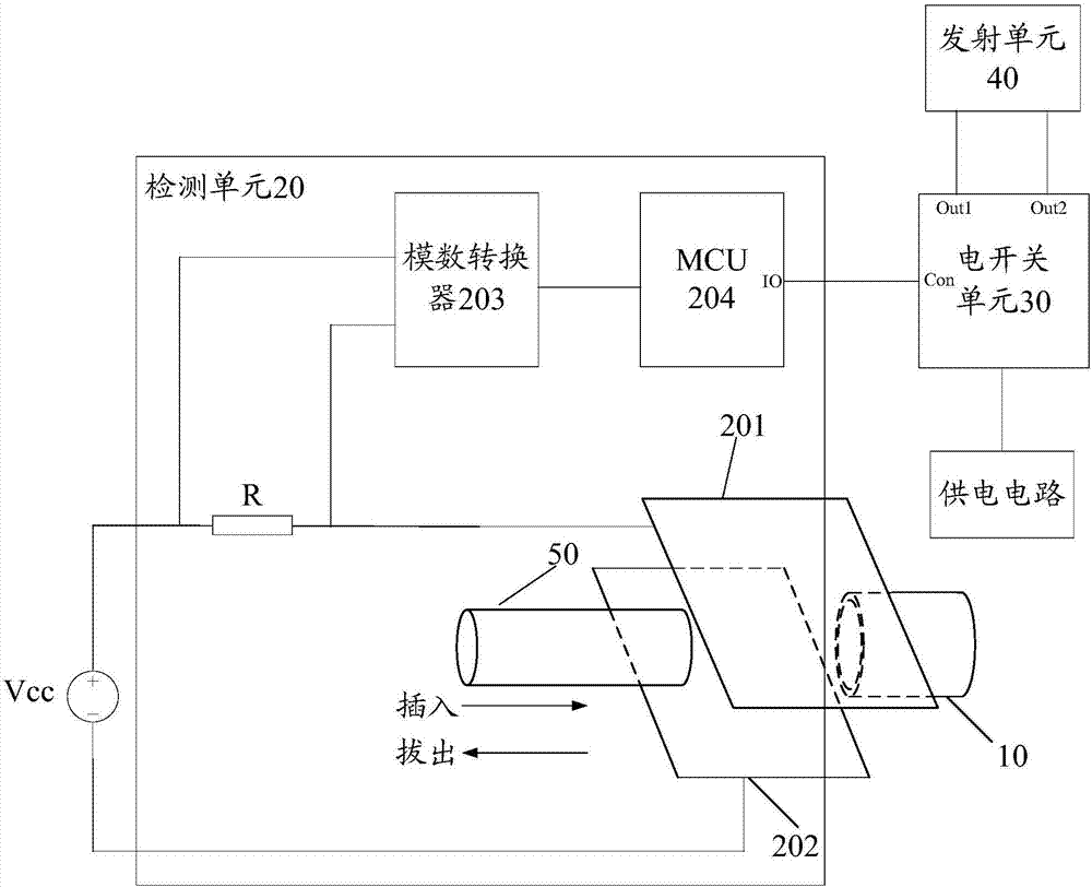
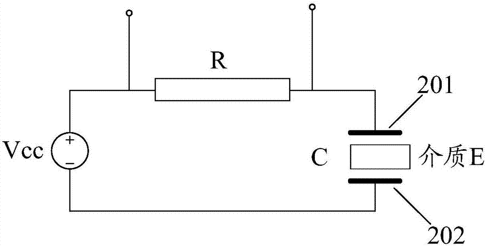
The application provides a light emitting device. The device includes an optical fiber interface, a detection unit, an electric switch unit and a transmission unit, wherein the detection unit is connected with the electric switch unit and is used for detecting the optical fiber plugging state of the optical fiber interface, when detecting that the optical fiber interface is inserted into an optical fiber, a closed signal is sent to the electric switch unit, and when detecting that the optical fiber is pulled out of the optical fiber interface, a disconnection signal is sent to the electric switch unit; the electric switch unit is connected between the transmission unit and a power supply circuit, is used for performing closing when receiving the closed signal sent by the detection unit toensure that the power supply circuit supplies power to the transmission unit, and is used for performing disconnection when receiving the disconnection signal sent by the detection unit to block the power supply of the power supply circuit to the transmission unit; and the transmission unit is connected with the optical fiber interface and is used for converting an electrical signal into an optical signal and emitting the optical signal on the optical fiber interface.

Description

technical field [0001] The present application relates to the technical field of optical communication, and in particular to an optical emitting device. Background technique [0002] The optical transmitter is a key device in optical communication equipment, and its main function is to convert electrical signals into optical signals and then emit them. At present, when the optical communication device is turned on, if no optical fiber is inserted into the optical fiber interface of the optical transmitting device, the optical transmitting device will still transmit optical signals through the optical fiber interface at this time. In this way, not only the energy of the optical communication equipment is wasted, additional heat is generated, but also additional laser pollution is caused. Contents of the invention [0003] In view of this, the present application provides a light emitting device. [0004] Specifically, this application is achieved through the following tec...

Claims


Application Information

Patent Timeline
Patent Type & Authority Applications(China)
IPC IPC(8): H04B10/50
CPCH04B10/50H04B10/503
Inventor 李韬李佳王成瑶
Owner NEW H3C TECH CO LTD
Why Eureka
Try Eureka