A high-precision large-span steelmaking bearing cantilever rotary table
A large-span, rotating table technology, applied in the direction of program control manipulators, manufacturing tools, manipulators, etc., can solve the problems of the robot's self-weight and working capacity limitations, to improve the work quality and ability, facilitate wiring, and improve cable life Effect
- Summary
- Abstract
- Description
- Claims
- Application Information
AI Technical Summary
Problems solved by technology
Method used
Image

Examples
specific Embodiment approach 1
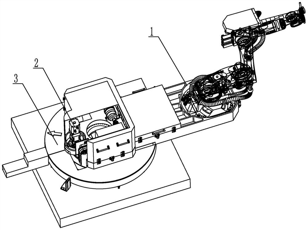
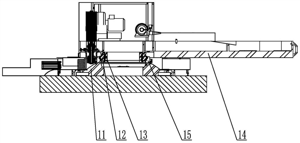
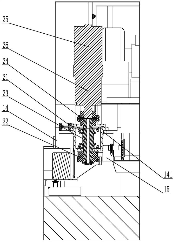
[0025] Specific implementation mode one: combine Figure 1 to Figure 11 Describe this embodiment. A high-precision and large-span steelmaking bearing cantilever rotary table described in this embodiment includes a cantilever bearing slewing arm 1, a precision adjustable meshing transmission device 2, and a vertical double-rotation radius drag chain box 3. The arm 1 includes a fixed base 11, a turntable bearing 12, a bearing transition piece 13, a large-span slewing arm 14 and a transmission ring gear 15, the fixed base 11 is arranged horizontally, and the transmission ring gear 15 is fixed on the upper end surface of the fixed base 11 , the outer ring of the turntable bearing 12 is fixed on the inner side of the transmission ring gear 15, the inner ring of the turntable bearing 12 is set on the lower part of the outer side of the bearing transition piece 13, and the rear end of the large-span slewing arm 14 is fixedly connected to the upper part of the bearing transition piece ...
specific Embodiment approach 2
[0034] Specific implementation mode two: combination Figure 9 To illustrate this embodiment, the box seat of the adjustable transmission shaft box 23 in this embodiment is provided with a plurality of elongated waist holes 231, and each elongated waist hole 231 is respectively arranged perpendicular to the tangential direction of the gear meshing. Backlash gear group 22 is connected with adjustable transmission shaft case 23 by fastening bolt, and fastening bolt is inserted in the elongated waist hole 231. Other compositions and connection methods are the same as those in Embodiment 1.
[0035] The box seat of the adjustable transmission shaft box 23 is provided with a strip-shaped waist hole 231. During operation, the center distance between the gap-adjusting gear set 22 and the transmission ring gear 15 can be adjusted according to the actual meshing conditions, so as to reduce the processing and installation of large castings. error, to achieve high-precision meshing.
specific Embodiment approach 3
[0036] Specific implementation mode three: combination Figure 2 to Figure 4 and Figure 10To illustrate this embodiment, the gap adjusting gear set 22 in this embodiment includes two gears 221 arranged side by side. There are two waist-shaped holes 223, each waist-shaped hole 223 is arranged along the circumferential direction, and the adjusting bolt 222 is inserted in the waist-shaped hole 223. Other compositions and connection modes are the same as those in Embodiment 1 or 2.
[0037] The size of the circumferential misalignment of the two gears 221 is adjusted by adjusting the bolt 222 to reduce the backlash distance of the meshing transmission. High-precision meshing transmission between the gap adjusting gear set 22 and the transmission ring gear 15 is realized.
PUM
 Abstract
Description
Claims
Application Information