Tire supporting component and tire assembly machine
An assembly machine and component technology, applied in tire installation, tire parts, vehicle parts, etc., can solve the problems of complex tire installation, time-consuming and labor-intensive, etc., and achieve the effect of improving installation efficiency, avoiding hand injuries, and reducing work intensity
- Summary
- Abstract
- Description
- Claims
- Application Information
AI Technical Summary
Problems solved by technology
Method used
Image

Examples
Embodiment 1
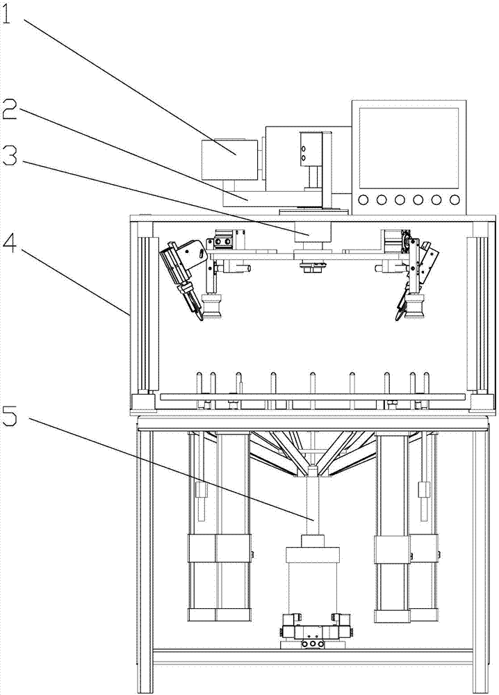
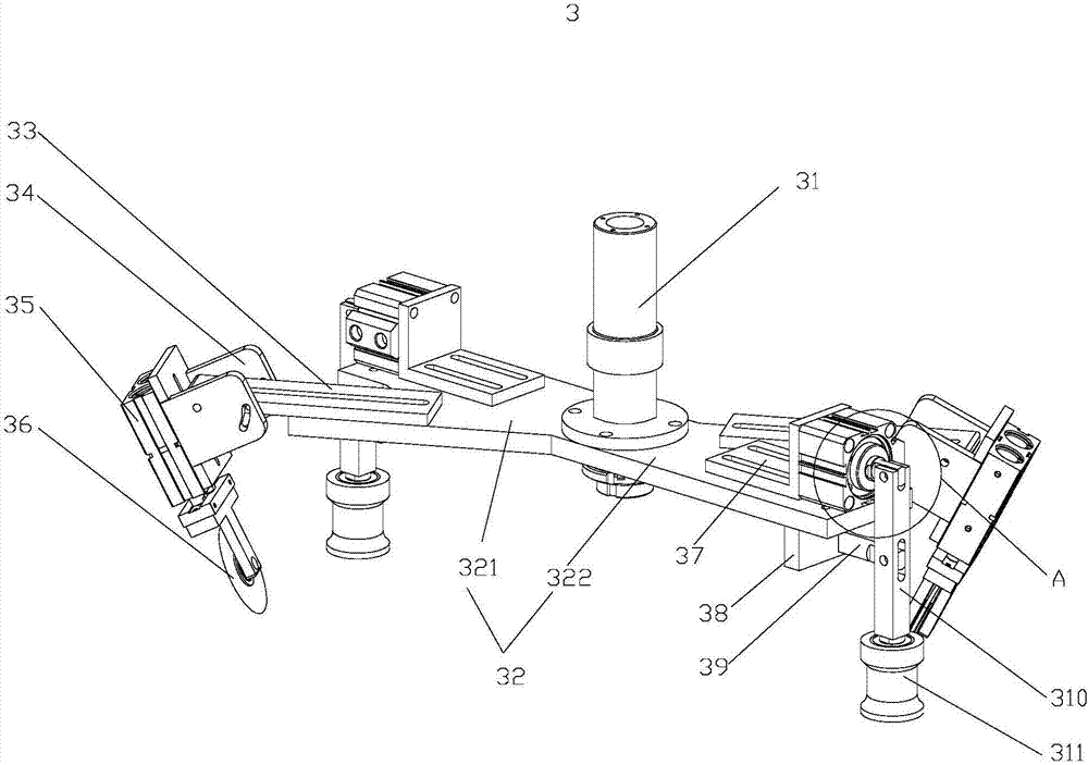
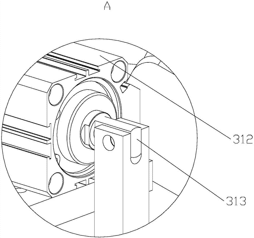
[0026] tire assembly machines such as Figure 1-7 As shown, the tire support assembly 5 is included, the tire support assembly 5 includes a chassis 571 and eight movable parts 57, the movable parts 57 include a movable rod 572, a trolley 574 and a pull rod 573, one end of the movable rod 572 is hinged with the chassis 571, and the movable rod 572 is another One end is hinged with the trolley 574, and the trolley 574 is provided with a pull rod 573. Also includes a third cylinder 59, the third cylinder 59 is provided with a third cylinder rod 58, the third cylinder rod 58 is connected with the chassis 571, and the third cylinder rod 58 drives the chassis 571 to move up and down. It also includes a first plate body 52 and a second plate body 51, the second plate body 51 is arranged above the first plate body 52, four pulleys 5741 are provided on the trolley 574, and the trolley 574 passes through the pulleys 5741 on the first plate body 52 Sliding upward, the pull rod 573 passe...
PUM
 Abstract
Description
Claims
Application Information