Mining jackdrill handle with shock absorption function

A technology for rock drills and handles, which is applied in the field of handles for mining rock drills, which can solve the problems of injuries to workers on rock drill handles, and achieve the effects of avoiding hand abrasions, reducing vibration, and protecting hands

Active Publication Date: 2018-12-18
平利县篮泰重晶石工贸有限公司
5 Cites 2 Cited by

AI-Extracted Technical Summary

Problems solved by technology

[0005] Aiming at the deficiencies of the prior art, the present invention provides a handle for mining rock drills with a shock-abs...

Method used

In summary, the mining rock drill handle with damping function, by being provided with a cross bar 9 between the moving plate 12 and the vertical plate 6, can use the The cross bar 9 is paired to promote the mobile plate 12. By being provided with an anti-slip sleeve 8 on the outer surface of the handle bar 7, the staff's hand can be avoided from being scratched, and the effect of protecting the staff's hand has been played. A short rod 16 is arranged between the slip rings 10, which can connect the stopper 15 and the second slip ring 10 together, and can move the horizontal plate 3 smoothly, making the device more stable. There is a first slip ring 13, which can slide the moving plate 12 left and right on the connecting rod 1, and a first spring 17 is arranged between the stopper 15 and the vertical plate 6, which can absorb shock when the horizontal plate 3 moves left and right and buffer function, to avoid excessive vibration of the device from impacting th...

Abstract

The invention discloses a mining jackdrill handle with the shock absorption function. The mining jackdrill handle with the shock absorption function comprises connecting rods. One end of each of the two connecting rods is fixedly connected with a stop block. The outer surfaces of the two connecting rods are both sleeved with limiting rings. The inner walls of the limiting rings are fixedly connected with the outer surfaces of the corresponding connecting rods. First sliding rings are inlaid in a moving plate. The connecting rods are sleeved with the corresponding first sliding rings. The innerwalls of the first sliding rings make contact with the outer surfaces of the corresponding connecting rods. The mining jackdrill handle with the shock absorption function can protect the hands of a worker against frazzle when the worker holds an antiskid sleeve to apply pressure to a jackdrill, plays a role in protecting the hands of the worker, can stably act on and move transverse plates, can enable the moving plate to slide left and right on the connecting rods, can achieve the shock absorption and buffering effects when the transverse plates move left and right and can have the bufferingeffect when applying pressure to the jackdrill to conduct drilling.

Application Domain

Metal-working hand tools

Technology Topic

Engineering

Image

  • Mining jackdrill handle with shock absorption function
  • Mining jackdrill handle with shock absorption function
  • Mining jackdrill handle with shock absorption function

Examples

  • Experimental program(1)

Example Embodiment

[0021] The technical solutions in the embodiments of the present invention will be clearly and completely described below in conjunction with the accompanying drawings in the embodiments of the present invention. Obviously, the described embodiments are only a part of the embodiments of the present invention, rather than all the embodiments. Based on the embodiments of the present invention, all other embodiments obtained by those of ordinary skill in the art without creative work shall fall within the protection scope of the present invention.
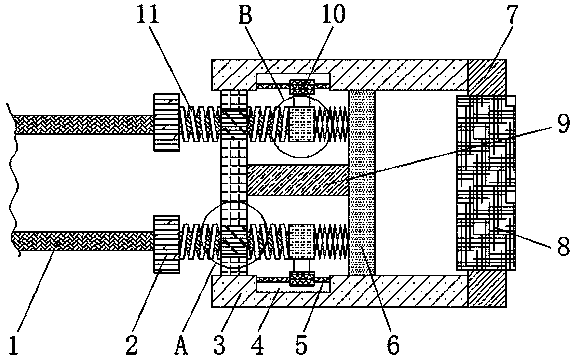
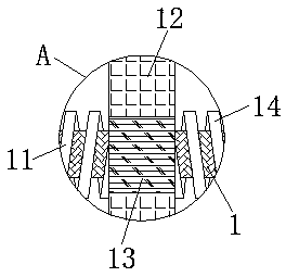
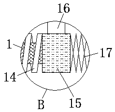
[0022] See Figure 1-3 , The present invention provides a technical solution: a handle for a mining rock drill with shock absorption function, comprising a connecting rod 1, the outer surface of the connecting rod 1 is sheathed with a second spring 11, the inner wall of the second spring 11 and the connecting rod 1 The outer surface of the rock drill is in contact with each other, and the second spring 11 is located between the stop ring 2 and the moving plate 12. By providing the second spring 11 between the stop ring 2 and the moving plate 12, it is possible to apply pressure to the rock drill for drilling It acts as a buffer at the same time, slowly progressing, effectively reducing the intensity of vibration, and effectively avoiding the danger of excessive force. The outer surface of the connecting rod 1 is covered with a third spring 14, and the inner wall of the third spring 14 is connected to the connecting rod 1. The outer surface meets, and the third spring 14 is located between the moving plate 12 and the stopper 15. By providing the third spring 14 between the moving plate 12 and the stopper 15, the vibration that occurs during rock drilling can be reduced When the hand grip device is driven to vibrate, it acts as a shock absorber. When the rock drill is taken out of the drill hole, it acts as a buffer. Both ends of the two connecting rods 1 are fixedly connected with a stopper 15, and the two connecting rods 1 A limit ring 2 is sleeved on the outer surface, and the inner wall of the limit ring 2 is fixedly connected to the outer surface of the connecting rod 1. The outer surface of the connecting rod 1 is provided with a moving plate 12, and the inside of the moving plate 12 is fixedly inlaid with a first sliding plate. Ring 13, the first slip ring 13 is sleeved with the connecting rod 1, the inner wall of the first slip ring 13 is in contact with the outer surface of the connecting rod 1, the moving plate 12 is located between the limit ring 2 and the stop 15, and the moving plate 12 Both ends of the two horizontal plates 3 are fixedly connected with a horizontal plate 3, and a groove 4 is provided on one side of the two horizontal plates 3 close to each other. The inside of the groove 4 is provided with a sliding rod 5, and both ends of the sliding rod 5 are connected to the groove respectively. The inner side wall of 4 is fixedly connected, the outer surface of the sliding rod 5 is sleeved with a second slip ring 10, and the inner wall of the second sliding ring 10 is in contact with the outer surface of the sliding rod 5, and the stop 15 is in contact with the second slip ring 10. A short rod 16 is provided therebetween, and both ends of the short rod 16 are respectively fixedly connected to the opposite side of the stopper 15 and the second slip ring 10, by providing a short rod between the stopper 15 and the second slip ring 10 16. The stopper 15 and the second slip ring 10 can be connected together, and the horizontal plate 3 can be moved smoothly, which makes the device more stable. A vertical plate 6 and a vertical plate 6 are arranged between the two horizontal plates 3 The two ends of the two horizontal plates 3 are respectively fixedly connected to the opposite side of the two horizontal plates 3, and the vertical plate 6 is located on the right side of the block 15, a horizontal rod 9 is provided between the movable plate 12 and the vertical plate 6, and the two horizontal rods 9 The ends are fixedly connected to the opposite side of the movable plate 12 and the vertical plate 6. By providing a cross bar 9 between the movable plate 12 and the vertical plate 6, the cross bar can be used when the anti-skid sleeve 8 is held to apply pressure to the rock drill. 9 pairs of pushing and moving plates 12, a first spring 17 is provided between the vertical plate 6 and the stop 15, and the two ends of the first spring 17 are respectively fixedly connected to the opposite side of the vertical plate 6 and the stop 15, two horizontal One end of the plate 3 is provided with a handle rod 7, and one side of the handle rod 7 is fixedly connected with one end of the two horizontal plates 3, the outer surface of the handle rod 7 is covered with a non-slip sleeve 8, and the non-slip sleeve 8 is located on the two horizontal plates. Between the plates 3, by providing a non-slip sleeve 8 on the outer surface of the handle rod 7, it can Enough to avoid the staff's hand abrasion, play a role in protecting the staff's hands.
[0023] Working principle: by holding the non-slip sleeve 8, place the rock drill at one end of the connecting rod 1 where the hole needs to be drilled. By applying pressure on the handle rod 7, the horizontal plate 3 drives the moving plate 12 to slide on the connecting rod 1, and the vertical plate is used The cross bar 9 on the side of 6 pushes the moving plate 12, using the elasticity of the first spring 17 and the second spring 11 to make the moving plate 12 play the role of shock absorption and buffering when moving, so as to avoid the danger of excessive force. When the rock drill is taken out from the eye after drilling, the third spring 14 is used to absorb shock and cushion, and the rock drill is gradually taken out to avoid injury.
[0024] In summary, the handle for a mining rock drill with shock absorption function is provided with a cross bar 9 between the moving plate 12 and the vertical plate 6, so that the cross bar 9 can be used when the anti-skid sleeve 8 is held to apply pressure to the rock drill. For the pushing and moving plate 12, the non-slip sleeve 8 is provided on the outer surface of the handle rod 7, which can avoid the staff's hand abrasion and protect the staff's hands. The stopper 15 and the second slip ring 10 There is a short rod 16 between it, which can connect the stop 15 and the second slip ring 10 together, and can move the horizontal plate 3 smoothly, so that the device has more stability. A slip ring 13, which can slide the moving plate 12 left and right on the connecting rod 1. By providing a first spring 17 between the stopper 15 and the vertical plate 6, it can absorb shock and cushion when the horizontal plate 3 moves left and right. To prevent excessive vibration of the device from impacting the staff through the handle rod 7, the second spring 11 is arranged between the stop ring 2 and the moving plate 12, which can play a buffering role when pressure is applied to the rock drill for drilling. , Slowly and gradually, effectively reduce the intensity of vibration, and effectively avoid the danger of excessive force. By setting the third spring 14 between the movable plate 12 and the stop 15, the vibration generated during rock drilling can drive the hand grip When the device vibrates, it acts as a shock absorber. When the rock drill is taken out of the drill hole, it acts as a buffer. By setting the limit ring 2 on the outer surface of the connecting rod 1, the external movement of the second spring 11 can be blocked. , To limit the moving length of the movable plate 12, by providing a stopper 15 at one end of the connecting rod 1, the vertical plate 6 can be blocked when the vertical plate 6 moves, and pressure is applied to the rock drill.
[0025] It should be noted that in this article, relational terms such as first and second are only used to distinguish one entity or operation from another entity or operation, and do not necessarily require or imply one of these entities or operations. There is any such actual relationship or order between.
[0026] Although the embodiments of the present invention have been shown and described, those of ordinary skill in the art can understand that various changes, modifications, and substitutions can be made to these embodiments without departing from the principle and spirit of the present invention. And variations, the scope of the present invention is defined by the appended claims and their equivalents.

PUM

no PUM

Description & Claims & Application Information

We can also present the details of the Description, Claims and Application information to help users get a comprehensive understanding of the technical details of the patent, such as background art, summary of invention, brief description of drawings, description of embodiments, and other original content. On the other hand, users can also determine the specific scope of protection of the technology through the list of claims; as well as understand the changes in the life cycle of the technology with the presentation of the patent timeline. Login to view more.

Similar technology patents

A disc type yarn tension device

ActiveCN103662979Bavoid hand injuryavoid yarn breakage
Owner:WUJIANG JIAWEI TEXTILE TECH CO LTD

Filter unit for kitchen sink

InactiveCN107447824Ahand protectionAvoid the influence of excessive water pressure and make it difficult to open the plug
Owner:江门市宝佳厨卫有限公司

Ceramic tile quality detection device

ActiveCN112108390AImprove work efficiencyavoid hand injury
Owner:佛山市科维骏机电设备有限公司

Automatic adhesive applying device for automotive center pillar plates

PendingCN107973169AFast glue applicationavoid hand injury
Owner:广东江友智能科技有限公司

Tire supporting component and tire assembly machine

ActiveCN107962920Aavoid hand injuryEven by force
Owner:杭州汇源自动化系统工程有限公司

Quick binding tourniquet for middle-aged and elderly people

ActiveCN110559039Ahand protection
Owner:JILIN UNIV FIRST HOSPITAL

Classification and recommendation of technical efficacy words

  • avoid hand injury
  • hand protection

Tire supporting component and tire assembly machine

ActiveCN107962920Aavoid hand injuryEven by force
Owner:杭州汇源自动化系统工程有限公司

Ceramic tile quality detection device

ActiveCN112108390AImprove work efficiencyavoid hand injury
Owner:佛山市科维骏机电设备有限公司

A disc type yarn tension device

ActiveCN103662979Bavoid hand injuryavoid yarn breakage
Owner:WUJIANG JIAWEI TEXTILE TECH CO LTD

Automatic adhesive applying device for automotive center pillar plates

PendingCN107973169AFast glue applicationavoid hand injury
Owner:广东江友智能科技有限公司

Quick binding tourniquet for middle-aged and elderly people

ActiveCN110559039Ahand protection
Owner:JILIN UNIV FIRST HOSPITAL

Filter unit for kitchen sink

InactiveCN107447824Ahand protectionAvoid the influence of excessive water pressure and make it difficult to open the plug
Owner:江门市宝佳厨卫有限公司
Why Eureka
Try Eureka