A disc type yarn tension device
A yarn tension, disc type technology, applied in the field of winders, can solve problems such as yarn breakage, and achieve the effect of avoiding yarn breakage and hand injury
- Summary
- Abstract
- Description
- Claims
- Application Information
AI Technical Summary
Problems solved by technology
Method used
Image

Examples
Embodiment Construction
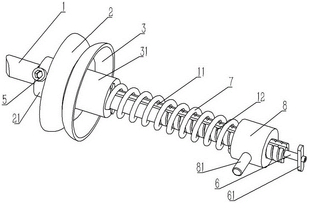
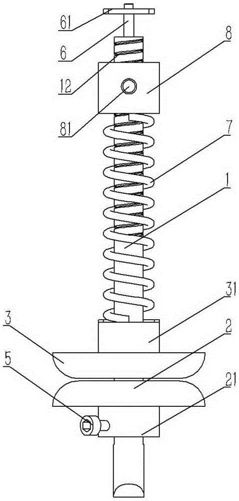
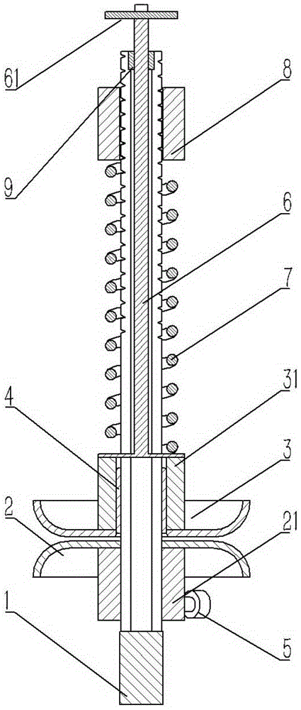
[0020] Example: see figure 1 , 2 , Shown in 3, a kind of disk-type yarn tensioning device comprises shaft rod 1, and shaft rod 1 is inserted with fixed disc 2 and movable disc 3, fixed disc 2 and movable disc 3 are respectively fixed with The first shaft sleeve 21 and the second shaft sleeve 31, the first shaft sleeve 21 of the fixed disc 2 is fixed on the shaft rod 1 by the set screw 5, and the second shaft sleeve 31 of the movable disc 3 is pressed against There is a compression spring 7, and the other end of the compression spring 7 is pressed against the adjustment sleeve 8, and the adjustment sleeve 8 is screwed on the shaft 1, and the front end surface of the shaft 1 is formed with cutting shaft 1 side walls Waist-shaped slot 11, the waist-shaped slot 11 of the shaft rod 1 is inserted with a T-shaped pull bar 6, and the head of the pull bar 6 is fixed on the second bushing 31 of the movable disc 3 and is located between the compression spring 7 and the first Between th...
PUM
 Abstract
Description
Claims
Application Information