

Ceramic tile quality detection device
A detection device and quality technology, applied in the field of ceramic tile quality detection devices, can solve the problems of troublesome operation, low work efficiency, easy hand injury, etc., and achieve the effect of high work efficiency, avoiding hand injury, and avoiding inability to reset in time.
- Summary
- Abstract
- Description
- Claims
- Application Information
AI Technical Summary
Problems solved by technology
Method used
Image

Examples
Embodiment 1
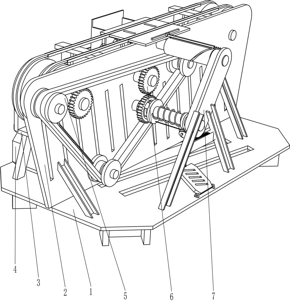
[0027] A tile quality detection device, such as Figure 1-Figure 4 As shown, it includes a base 1, a vertical plate 2, a horizontal plate 3, a motor 4, a transmission mechanism 5, and a lifting mechanism 6. The vertical plate 2 is fixed in the middle of the top of the base 1, and the middle part of the left side of the vertical plate 2 is connected to the top of the base 1. A horizontal plate 3 is fixed between the left sides, a fixed plate 21 is fixed on the left side of the top of the horizontal plate 3, a motor 4 is fixed on the left front of the top of the base 1, and a transmission mechanism is provided between the fixed plate 21 and the vertical plate 2 5. The transmission mechanism 5 is fixedly connected to the end of the output shaft of the motor 4 , and a jacking mechanism 6 is provided between the vertical plate 2 and the fixed plate 21 , and the jacking mechanism 6 is in contact with the transmission mechanism 5 .
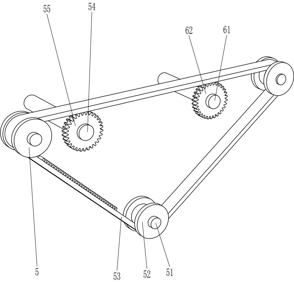
[0028]The transmission mechanism 5 includes a firs...
Embodiment 2
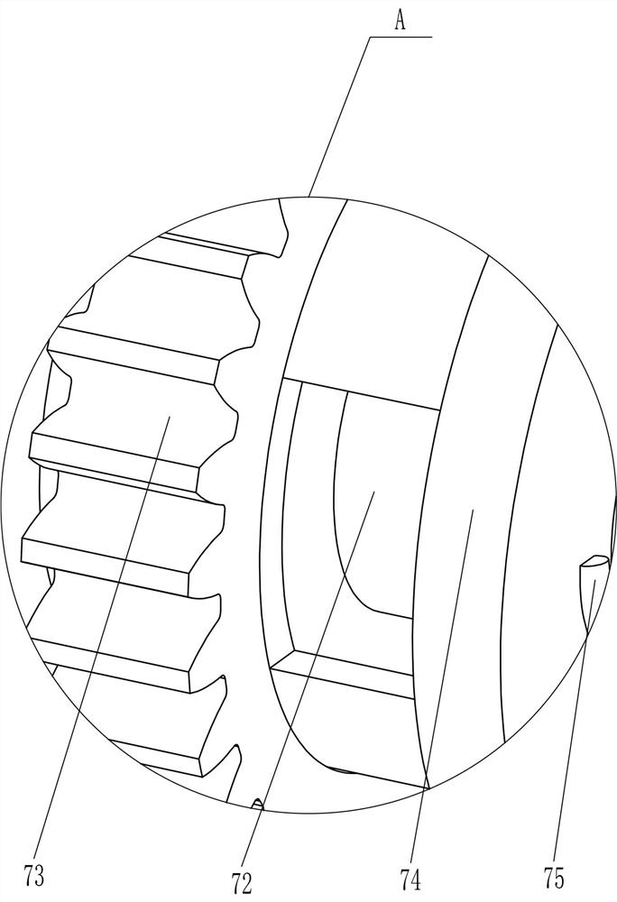
[0034] On the basis of Example 1, such as figure 2 , Figure 5 , Figure 6 , Figure 7 and Figure 8 Shown, also comprise pusher mechanism 7, pusher mechanism 7 includes support frame 71, the 4th transmission shaft 72, the 3rd gear 73, pull ring 74, compression spring 75, guide wheel 76, pedal 77, steel wire rope 78, Second drive belt 79, spiral groove roller 710, push rod 711, roller 712, extension spring 713 and waste box 714, base 1 top right middle part is affixed with support frame 71, support frame 71 left side middle parts and There is a fourth power transmission shaft 72 that is rotated between the front side of the middle part of the right side of the vertical plate 2. The left part of the fourth power transmission shaft 72 is octagonal in circumference, and the fourth power transmission shaft 72 is octagonal. Three gears 73, the third gear 73 cooperates with the toothed transmission belt 53, the left part of the fourth transmission shaft 72 is slidably fitted wi...
Embodiment 3
[0037] On the basis of embodiment 1 and embodiment 2, such as Figure 4 As shown, a return spring 8 is also included, and the return spring 8 is wound between the bottom of the guide support plate 67 and the lower part of the ejector rod 66 .
[0038] Also include roller 9, the bottom end of ejector rod 66 is rotatably provided with roller 9, and roller 9 cooperates with projection 65.
[0039] When the forward rotation of the bump 65 drives the ejector rod 66 to move upward, the reset spring 8 is compressed, and then the bump 65 continues to rotate forwardly and disengages from the ejector rod 66. Due to the action of the return spring 8, the ejector rod 66 moves downward to reset . In this way, it can be avoided that the ejector rod 66 cannot be reset in time, which will affect the follow-up work.
[0040] When the bump 65 rotates forward and contacts the ejector rod 66, the bump 65 forwardly rotates and drives the ejector rod 66 to move upward through the roller 9, so tha...
PUM
 Abstract
Description
Claims
Application Information