
Rotor armed unmanned aerial vehicle

A technology of unmanned rotor and unmanned aerial vehicle, which is applied in the application field of rotor unmanned aerial vehicle and weapons, can solve the problems of harshness, matching and mounting of unmanned aerial vehicles and weapons, and achieves reasonable matching, simple and convenient mounting method, and structural layout. compact effect

Inactive Publication Date: 2018-04-27
牟正芳
View PDF0 Cites 22 Cited by
  • Summary
  • Abstract
  • Description
  • Claims
  • Application Information

AI Technical Summary

Problems solved by technology

Due to the harsh environment in which the rotor UAV is used as a weapon platform to carry weapons, there is currently no rotor armed UAV with real combat significance. In particular, it is necessary to solve the matching problems between UAVs and weapons, mounting problems and weapon control problems.

Method used


Image

  • Rotor armed unmanned aerial vehicle
  • Rotor armed unmanned aerial vehicle
  • Rotor armed unmanned aerial vehicle

Examples


Embodiment Construction

[0022] In the following description, many specific details are set forth in order to fully understand the present invention, but the present invention can also be implemented in other ways different from those described here. Obviously, the described embodiments are only a part of the embodiments of the present invention , not all embodiments, so the present invention is not limited by the specific embodiments disclosed below. Based on the embodiments of the present invention, all other embodiments obtained by those skilled in the art without creative efforts fall within the protection scope of the present invention. The specific implementation manners of the present invention will be described in detail below in conjunction with the accompanying drawings.

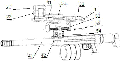
[0023] Such as figure 1 As shown, the overall structure of the rotor armed UAV. Rotor UAV fuselage 1 is the flight carrying platform of rotor armed UAV; the observation and aiming unit includes camera 21, range finder 22...


PUM


Abstract

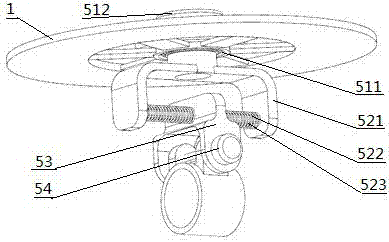
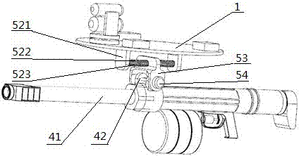
The invention discloses a rotor armed unmanned aerial vehicle which comprises an unmanned gyroplane, an observing and aiming unit, a mounting unit, a weapon unit and a control unit. An unmanned gyroplane body is a bearing platform of the rotor armed unmanned aerial vehicle, and the observing and aiming unit observes, measures and aims at a target. The mounting unit comprises a direction adjustingmechanism, a buffering mechanism, a mounting block and a high-low angle adjusting mechanism. The direction adjusting mechanism comprises a bearing ring and a driving motor. The buffering mechanism isconnected with the rotating bearing ring, and a guide rod penetrates through a guide hole in the upper portion of the mounting block. The two ends of the guide rod are fixed to a supporting seat, andsprings are arranged at the two ends of the guide rod in a sleeving mode to constrain the mounting block to achieve the buffering effect. The upper portion of the mounting block is connected with theguide rod of the buffering mechanism, and the lower portion of the mounting block is provided with the high-low angle adjusting mechanism. According to the rotor armed unmanned aerial vehicle, the mounting mode is simple and convenient, a control mechanism is compact and reliable, and the buffering mechanism is efficient and reliable; through the mounted observing and aiming unit, the all-weatherfighting ability is achieved; through the control unit, the target can be remotely monitored and accurately struck, and thus the safety of obverse shooter is effectively ensured.

Description

technical field [0001] The invention relates to the field of rotor unmanned aerial vehicles and weapon applications, in particular to a rotor unmanned aerial vehicle equipped with weapons capable of attacking ground or air. Background technique [0002] Rotary-wing UAVs include single-rotor, dual-rotor and multi-rotor UAVs, which have the advantages of convenient take-off and landing, flexible maneuvering, easy concealment, and relatively low cost. Driven by the national strategy of in-depth development of military-civilian integration, it is introduced and used It is very promising in the field of military equipment, and it is very in line with the current and future development needs of unmanned, miniaturized, and modular military equipment. [0003] With the improvement of the technical level of the rotor UAV, the rotor UAV is more and more capable of carrying weapons as a weapon platform. If the rotor UAV platform is equipped with weapons and becomes a rotor armed UAV, i...

Claims


Application Information

Patent Timeline
Patent Type & Authority Applications(China)
IPC IPC(8): B64C39/02B64D7/00B64D7/06B64D7/08
CPCB64C39/02B64D7/00B64D7/06B64D7/08B64U2101/00
Inventor 刘涛
Owner 牟正芳
Learn More