Automatic crimping mechanism and automatic crimping device

A mobile mechanism, automatic technology, applied in the direction of measuring devices, machine/structural parts testing, instruments, etc., can solve the problems of inaccurate automatic alignment and crimping, incomplete function realization, etc., to save labor costs, improve production efficiency, The effect of precise alignment and crimping

Pending Publication Date: 2018-04-27
KUSN JINGXUN ELECTRONICS TECH
View PDF7 Cites 4 Cited by
  • Summary
  • Abstract
  • Description
  • Claims
  • Application Information

AI Technical Summary

Problems solved by technology

[0004] The technical problem to be solved by the present invention is: to solve the problem in the prior art that the automatic alignment and crimping of FFC and FPC is not accurate, so that the function is not fully realized

Method used


Image

  • Automatic crimping mechanism and automatic crimping device
  • Automatic crimping mechanism and automatic crimping device
  • Automatic crimping mechanism and automatic crimping device

Examples


Embodiment 1

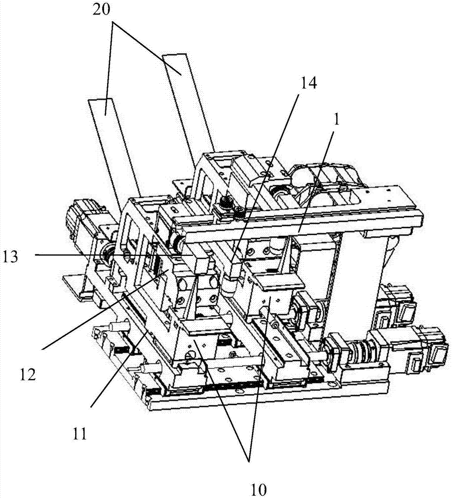
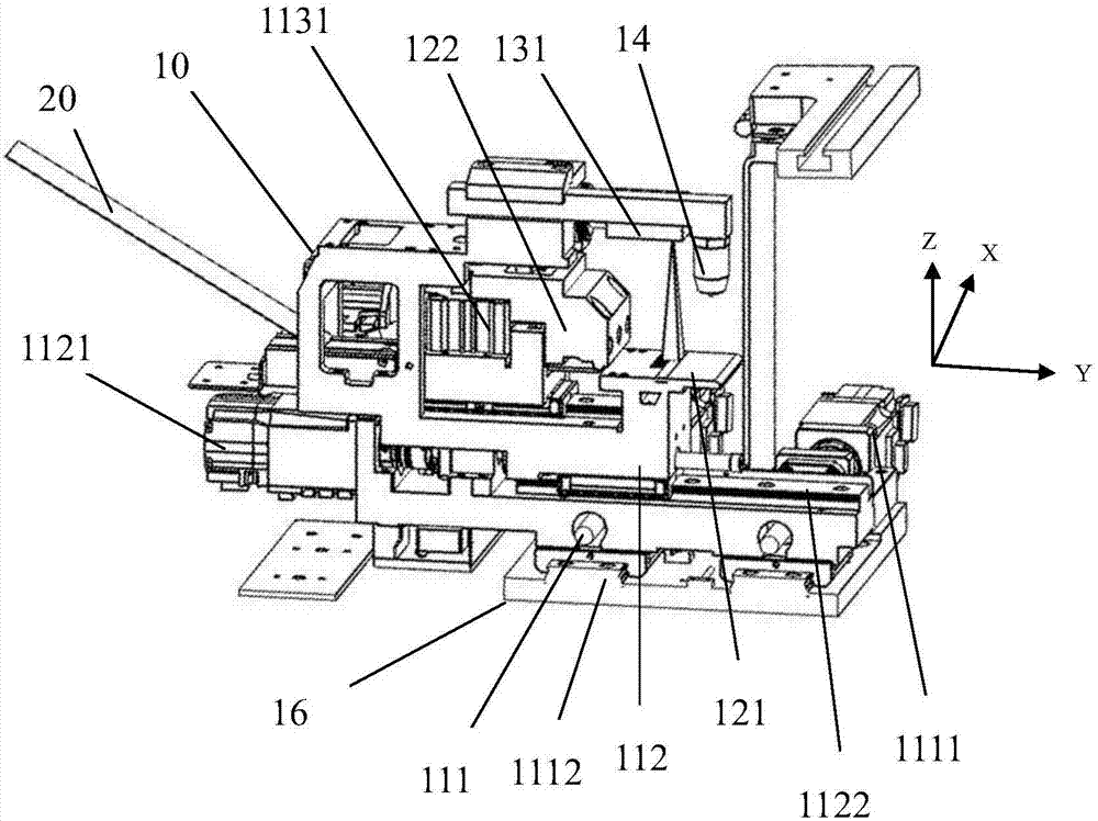
[0029] Such as figure 2 As shown, this embodiment provides an automatic crimping mechanism for panel point screen detection, including a moving mechanism 11, an indenter module 12 and an image system 13; the indenter module 12 is fixed on the moving mechanism 11 Above, as the moving mechanism 11 moves, the imaging system 13 is arranged above the indenter module 12, and the indenter module 12 and the imaging system 13 can move with the moving mechanism 11; The image system 13 obtains the relative position of the indenter 122 of the indenter module 12 and the panel test pad through the camera 131, and the indenter module 12 is used to connect the flexible circuit board 20 connecting the test signal to the panel The test pad is crimped.

[0030] The flexible circuit board 20 is driven to move by the moving mechanism. At the same time, the image system is used to collect and judge whether the positions of the test pad and the flexible circuit board 20 are aligned in real time. ...

Embodiment 2

[0040] The difference between this embodiment and embodiment one is:

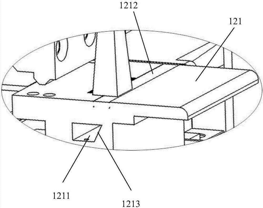
[0041] Such as image 3 As shown, there is a transparent part 1212 on the crimping platform 121, and a bearing groove 1213 is provided under the transparent part, and a backlight 1211 is installed in the bearing groove 1213 for assisting the imaging system 13 to take pictures.

[0042] The backlight 1211 enables the imaging system 13 to take pictures more clearly, thereby improving the accuracy of the imaging system 13 in judging the positions of the flexible circuit board 20 and the test pad, and avoiding misjudgment and misalignment of the two.

Embodiment 3

[0044] The difference between this embodiment and embodiment one is:

[0045] An air blowing system 14 is also included, the air blowing system 14 is slidably connected to the moving mechanism 11 and located above the crimping platform 121 for blowing air to the crimping platform 121 . The wind pressure forces the flexible circuit board 20 and the test pad to be flattened on the crimping platform, thereby improving the accuracy of the imaging system in judging the position of the flexible circuit board 20 and the test pad, and avoiding problems caused by warping or unevenness of the flexible circuit board 20 and the test pad. The occurrence of the problem of inaccurate judgment of its position.


PUM


Abstract

The invention relates to an automatic crimping mechanism which is used for panel point screen detection. The automatic crimping mechanism comprises a mobile mechanism, a pressure head module group andan image system. The pressure head module group is fixed on the mobile mechanism. The image system is arranged on the pressure head module group, and the pressure head module group and the image system can move along with the mobile mechanism. The image system is used for acquiring the relative position of the pressure head of the pressure head module group and a panel test cushion. The pressurehead module group is used for crimping the flexible circuit board connecting the test signal and the panel test cushion. According to the automatic crimping mechanism, full-automatic accurate alignment and crimping of the flexible circuit board and the test cushion can be realized so that the alignment and crimping accuracy of the flexible circuit board and the test cushion can be greatly enhanced, the manpower cost can be saved and the production efficiency can be enhanced.

Description

technical field [0001] The invention relates to the field of panel detection, in particular to an automatic crimping mechanism and an automatic crimping device for panel detection. Background technique [0002] During the production process of the display panel, multiple processes require point-screen inspection of the panel to determine whether certain qualities of the panel meet the production requirements. For a panel that has not been bound to a PCB (Printed Circuit Board, printed circuit board), the detection signal input of this type of panel is realized by directly crimping the probe of the detection device with the metal test pad on the panel; and For a panel that has undergone PCB bonding, the detection signal input is realized by crimping the probe of the detection device with the gold finger of the PCB or the gold finger of the FFC (Flexible Flat Cable) on the panel. [0003] In the prior art, the above two kinds of crimping are usually realized in a semi-automat...

Claims


Application Information

Patent Timeline
Patent Type & Authority Applications(China)
IPC IPC(8): G01M11/00G01R31/00
CPCG01M11/00G01R31/00
Inventor 于伟叶坤商秋锋
Owner KUSN JINGXUN ELECTRONICS TECH
Why Eureka
Try Eureka