An automatic crimping method

An automatic, indenter technology, used in instruments, measuring devices, electronic circuit testing, etc., can solve the problems of inaccurate automatic alignment and crimping, incomplete function realization, etc., to save labor costs, improve production efficiency, and improve accuracy. Effect

Active Publication Date: 2021-02-05
KUSN JINGXUN ELECTRONICS TECH
View PDF12 Cites 0 Cited by
  • Summary
  • Abstract
  • Description
  • Claims
  • Application Information

AI Technical Summary

Problems solved by technology

[0003] The technical problem to be solved by the present invention is: to solve the problem in the prior art that the automatic alignment and crimping of FFC and FPC is not accurate, so that the function is not fully realized

Method used


Image

  • An automatic crimping method
  • An automatic crimping method
  • An automatic crimping method

Examples


Embodiment 1

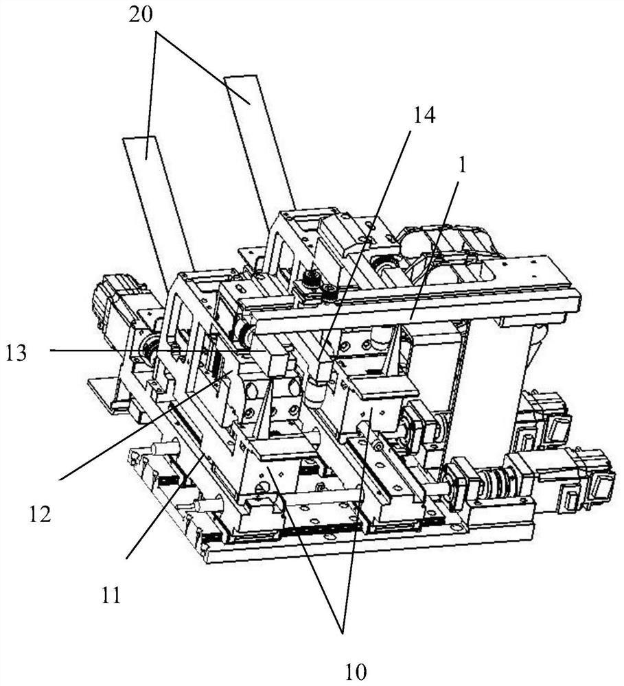
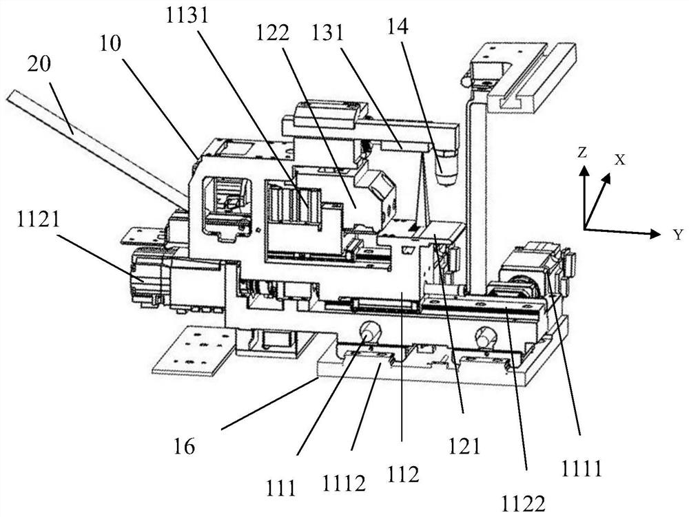
[0037] Such as figure 2 As shown, this embodiment provides an automatic crimping mechanism for panel point screen detection, including a moving mechanism 11, an indenter module 12 and an image system 13; the indenter module 12 is fixed on the moving mechanism 11 Above, as the moving mechanism 11 moves, the imaging system 13 is arranged above the indenter module 12, and the indenter module 12 and the imaging system 13 can move with the moving mechanism 11; The image system 13 obtains the relative position of the indenter 122 of the indenter module 12 and the panel test pad through the camera 131, and the indenter module 12 is used to connect the flexible circuit board 20 connecting the test signal to the panel The test pad is crimped.

[0038] The flexible circuit board 20 is driven to move by the moving mechanism. At the same time, the image system is used to collect and judge whether the positions of the test pad and the flexible circuit board 20 are aligned in real time. ...


PUM


Abstract

The present invention relates to an automatic crimping method. The method comprises the steps of: providing an automatic crimping structure; fixing a flexible circuit board at a crimping platform of the automatic crimping structure; putting a test terminal of a panel on the crimping platform; determining whether a relative position of a golden finger of the flexible circuit board and a test pad ofthe panel reaches a pre-determined relative position or not; moving the golden finger of the flexible circuit board until the relative position of the golden finger of the flexible circuit board andthe test pad of the panel reaches the pre-determined relative position; moving the flexible circuit board for a preset distance in a Y direction to allow the golden finger of the flexible circuit board to directly face the test pad of the panel; and moving downwards a pressing head module, and compacting the golden finger of the flexible circuit board with the test pad of the panel. The automaticcrimping method achieves automatic and accurate aligning crimping of the flexible circuit board and the test pad so as to greatly improve the accuracy of the aligning crimping of the flexible circuitboard and the test pad, save the human cost and improve the production efficiency.

Description

technical field [0001] The invention relates to the field of panel detection, in particular to an automatic crimping method for panel detection. Background technique [0002] During the production process of the display panel, multiple processes require point-screen inspection of the panel to determine whether certain qualities of the panel meet the production requirements. For a panel that has not been bound to a PCB (Printed Circuit Board, printed circuit board), the detection signal input of this type of panel is realized by directly crimping the probe of the detection device with the metal test pad on the panel; and For a panel that has undergone PCB bonding, the detection signal input is realized by crimping the probe of the detection device with the gold finger of the PCB or the gold finger of the FFC (Flexible Flat Cable) on the panel. In the prior art, the above two kinds of crimping are usually realized in a semi-automatic manner. Although the alignment and crimpin...

Claims


Application Information

Patent Timeline
Patent Type & Authority Patents(China)
IPC IPC(8): G01R31/28
CPCG01R31/2825
Inventor 于伟叶坤商秋锋
Owner KUSN JINGXUN ELECTRONICS TECH
Why Eureka
Try Eureka