Spliced directional backlight source and display system using same

A display system and backlight technology, applied in the direction of nonlinear optics, optics, optical components, etc., can solve the problems of depth limitation, viewing angle limitation, etc., achieve the effect of expanding viewing angle, eliminating dark areas, and realizing adjustability

Pending Publication Date: 2018-04-27
GUANGZHOU MIDSTERO TECH CO LTD
View PDF5 Cites 7 Cited by
  • Summary
  • Abstract
  • Description
  • Claims
  • Application Information

AI Technical Summary

Problems solved by technology

[0005] In order to solve the deficiencies in the prior art, the object of the present invention is to provide a splicing type directional backlight and a display system using the backlight, aiming at eliminating the dark area existing in the viewing area in the existing naked-eye 3D display system, and Solve the problems of limited viewing angle and limited depth when viewing 3D images

Method used


Image

  • Spliced directional backlight source and display system using same
  • Spliced directional backlight source and display system using same
  • Spliced directional backlight source and display system using same

Examples


Embodiment 1

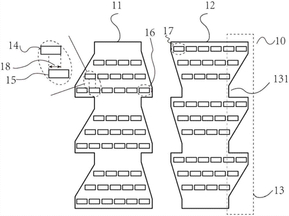
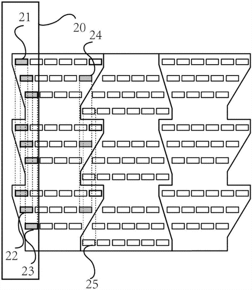
[0041] like figure 1The structure of a spliced ​​directional backlight shown in -4 mainly includes: a plurality of spliced ​​substrates 10 , several light-emitting areas and a light-diffusing film layer 30 .

[0042] Splicing structures 13 are provided on both sides of the splicing substrate 10 , and the splicing structures 13 are used for splicing and extending the splicing substrates 10 . The splicing structure 13 is a gap 131 arranged at intervals on both sides of the splicing substrate 10, and complementary splicing is completed between the splicing substrates 10 through the gap 131, and the gap 131 can be set in a triangle, rectangle, trapezoid, polygon or any of the circles.

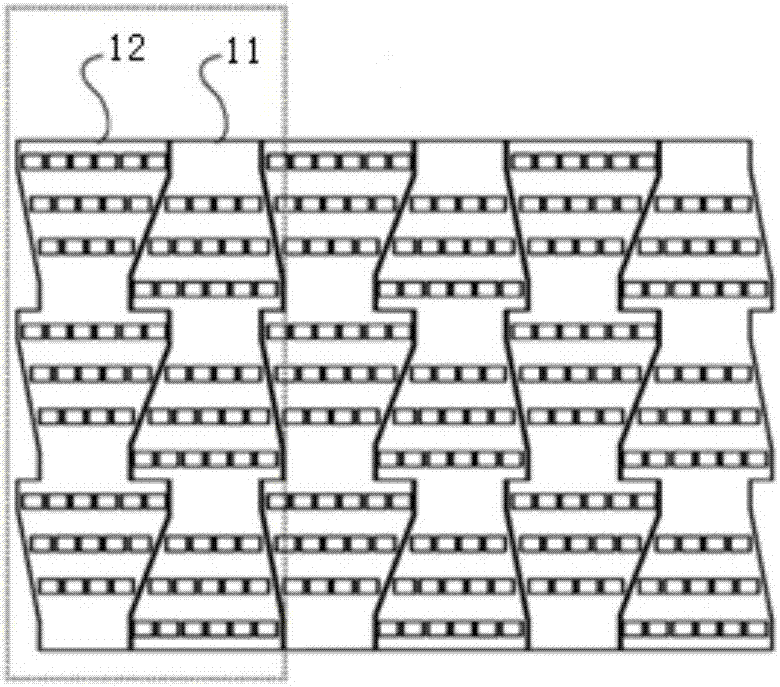
[0043] Preferably, the splicing structure 13 is arranged in a triangular zigzag shape, the splicing substrate 10 includes a first substrate 11 and a second substrate 12, the left side of the first substrate 11 and the left side of the second substrate 12 The right side can be complementary connec...

Embodiment 2

[0050] The similarities with the above-mentioned solutions will not be described in detail. As another preferred specific implementation mode, in this embodiment, the arc-shaped splicing type directional backlight and the Figure 5b In the naked-eye 3D display system 50 equipped with an arc splicing type directional backlight as shown, the splicing substrates 10 are spliced ​​with each other to form an arc, and the light-emitting area is arranged inside the arc; the arc splicing type The directional backlight 51 is alternately spliced ​​by several first substrates 11 and second substrates 12 into an arc with a certain radian and radius of curvature, and a light diffusion film layer 30 is placed a certain distance in front of the light-emitting area. Therefore, through the first substrate 11 and the For the splicing of the second substrate 12, the light-emitting areas are continuously and staggered along the lateral direction; the light diffusion film layer 30 is arranged in fro...


PUM

PropertyMeasurementUnit
angleaaaaaaaaaa

Abstract

The invention discloses a spliced directional backlight source and a display system using the same. The spliced directional backlight source includes splicing substrates, a plurality of light emittingareas, and a light diffusion film layer. Each splicing substrate is provided with splicing structures on the two sides thereof, and the splicing structures are used to splice and extend the splicingsubstrates. The light emitting areas are distributed on the splicing substrates. The adjacent light emitting areas are at least partially in staggered distribution in the transverse direction, and areindependently distributed in the longitudinal direction. A light source with the light emitting areas in continuous and staggered distribution in the transverse direction is formed through splicing and extending. The light diffusion film layer is arranged corresponding to the light source. The light diffusion film layer is arranged in front of the splicing substrates to form a backlight source. Alens array is arranged in front of the backlight source. A liquid crystal display layer is arranged corresponding to the backlight source. The other side of the liquid crystal display layer is an observation area. The invention aims to eliminate the dark area in the visual area of the existing naked eye 3D display system and to solve the problem that the viewing angle and depth are limited in 3Dvideo watching.

Description

technical field [0001] The invention belongs to the field of backlight equipment design, and more specifically relates to a spliced ​​directional backlight and a display system using the backlight. Background technique [0002] At present, the directional backlight technology is one of the mainstream glasses-free 3D stereoscopic display technologies. The basic principle of directional backlight display technology is to adopt the method of time-space multiplexing, and use optical devices to control the propagation of light to a certain extent, forming a series of viewing areas that can be switched independently at the viewing distance. Equipped with a liquid crystal display panel with a high refresh rate, when the observer's eyes are in any viewing area, turn on the lighting of the viewing area, and the image currently displayed on the liquid crystal display panel can be viewed; when the observer's eyes are in the viewing area When the camera is outside, the image on the LCD...

Claims


Application Information

Patent Timeline
Patent Type & Authority Applications(China)
IPC IPC(8): G02B27/22G02F1/13357
CPCG02F1/1336G02F1/133606G02B30/24G02F1/133607
Inventor 李焜阳陈学浩陈铭俊丁锐杰梁伟棠李晓克范杭
Owner GUANGZHOU MIDSTERO TECH CO LTD
Why Eureka
Try Eureka