Display module and electronic device
A display module and display module technology, applied in character and pattern recognition, instrument, print image acquisition, etc., can solve problems such as complex structure of the display module, and achieve the effect of accurate recognition, high reliability and simple structure
- Summary
- Abstract
- Description
- Claims
- Application Information
AI Technical Summary
Problems solved by technology
Method used
Image


Examples
no. 1 example
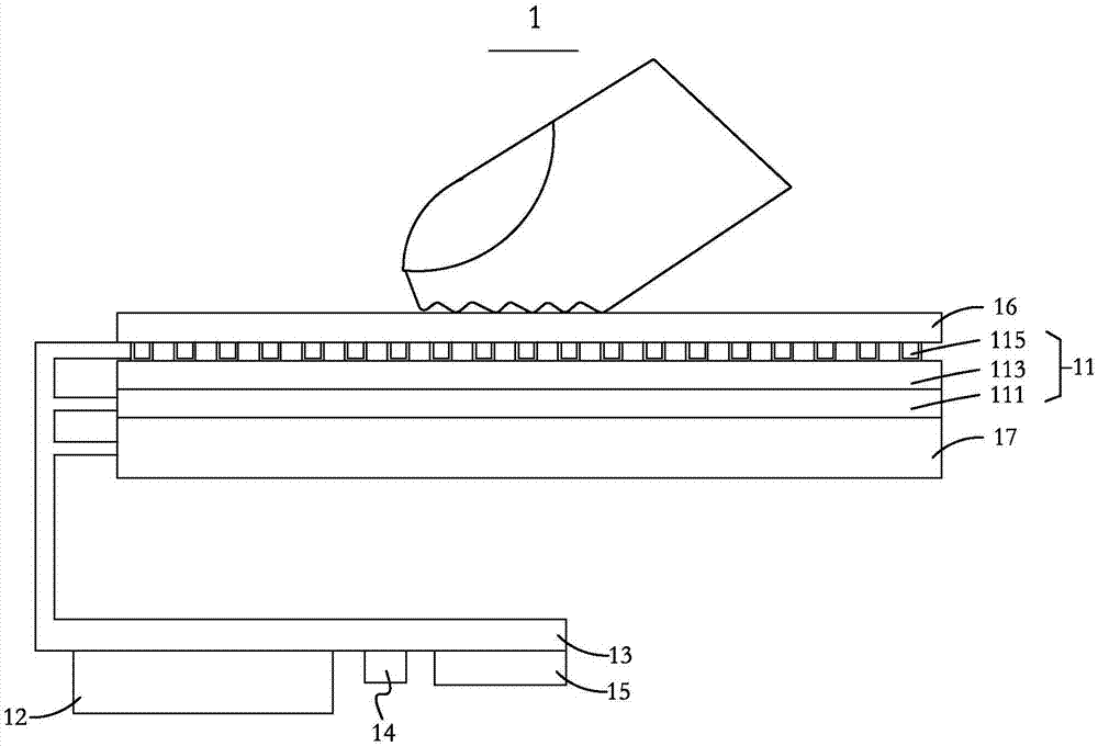
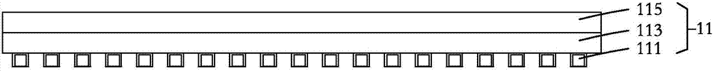
[0029] Please refer to Figure 1A , 1B and 1C, the first embodiment of the present invention provides a display module 1, which includes an identification module 11, a cover plate 16, a control module 12, a circuit board 13, a separation device 14, a connector 15 and a display module 17. The display side of the display module 17 is the display side, the identification module 11 and the display module 17 are stacked, and the identification module 11 is fixed on the display side of the display module 17 . The cover plate 16 is disposed on the identification module 11 and located on a side of the identification module 11 away from the display module 17 , and the cover plate 16 completely covers the identification module 11 . The side of the cover plate 16 away from the identification module is the touch side, which can be touched by fingers. The circuit board 13 is electrically connected to the control module 12 , and the circuit board 13 is also electrically connected to the i...
no. 2 example
[0052] see figure 2, the second embodiment of the present invention provides a display module 2, the display module 2 includes an identification module 21, a cover plate 26, a control module 22, a circuit board 23, a separation device 24, a connector 25, a display module 27 and Ultrasonic emission module 28. The identification module 21 and the ultrasonic emission module 28 are respectively located on opposite sides of the display module 27 . The side of the display module 27 used for display is the display side, and the ultrasonic emission module 28 is arranged on the side of the display module 27 away from the display side. The cover plate 26 is disposed on the identification module 21 and located on a side of the identification module 21 away from the display module 27 , and the cover plate 26 completely covers the identification module 21 . The circuit board 23 is electrically connected to the control module 22 , and the circuit board 23 is also electrically connected t...
no. 3 example
[0070] see image 3 , The second embodiment of the present invention provides a display module 3 , the display module 3 includes an identification module 31 , a cover 36 , a control module 32 , a circuit board 33 , a separation device 34 , a connector 35 and a display module 37 . The display side of the display module 37 is the display side, and the identification module 31 is disposed on the display side of the display module 37 . The cover plate 36 is disposed on the identification module 31 and located on a side of the identification module 31 away from the display module 37 , and the cover plate 36 completely covers the identification module 31 . The circuit board 33 is electrically connected to the control module 32 , and the circuit board 33 is also electrically connected to the identification module 31 , the display module 37 , the separating device 34 and the connector 35 . The circuit board 33 , the control module 32 , the separating device 34 and the connector 35 ar...
PUM
 Abstract
Description
Claims
Application Information
 - R&D
- Intellectual Property
- Life Sciences
- Materials
- Tech Scout
- Unparalleled Data Quality
- Higher Quality Content
- 60% Fewer Hallucinations
Browse by: Latest US Patents, China's latest patents, Technical Efficacy Thesaurus, Application Domain, Technology Topic, Popular Technical Reports.
© 2025 PatSnap. All rights reserved.Legal|Privacy policy|Modern Slavery Act Transparency Statement|Sitemap|About US| Contact US: help@patsnap.com