Installation device and installation method

A technology of installation device and installation position, applied in the direction of electrical components, electrical components, etc., can solve the problems of high production line cost, large-scale device, production takt delay, etc., and achieve the effect of improving production takt

Active Publication Date: 2018-04-27
JUKI CORP
View PDF12 Cites 5 Cited by
  • Summary
  • Abstract
  • Description
  • Claims
  • Application Information

AI Technical Summary

Problems solved by technology

[0005] However, in the mounting device described in Patent Document 1, a variety of components can be automatically mounted on a board by an articulated robot, but it is necessary to install a production line for temporary placement in addition to the production line for mounting, so the structure of the device becomes It is complicated and the device is enlarged
Therefore, a sufficiently wide installation space is required, and the installation place of the installation device is limited.
In addition, since the operation is performed in two stages of the temporary placement operation by the first articulated robot and the mounting operation by the second articulated robot, there is a problem that the production cycle is delayed and the cost of the production line is increased.

Method used


Image

  • Installation device and installation method
  • Installation device and installation method
  • Installation device and installation method

Examples


Embodiment Construction

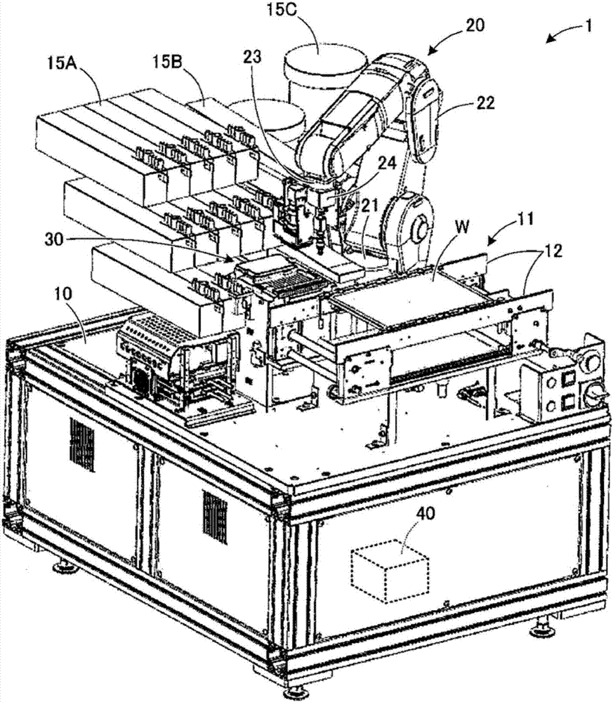
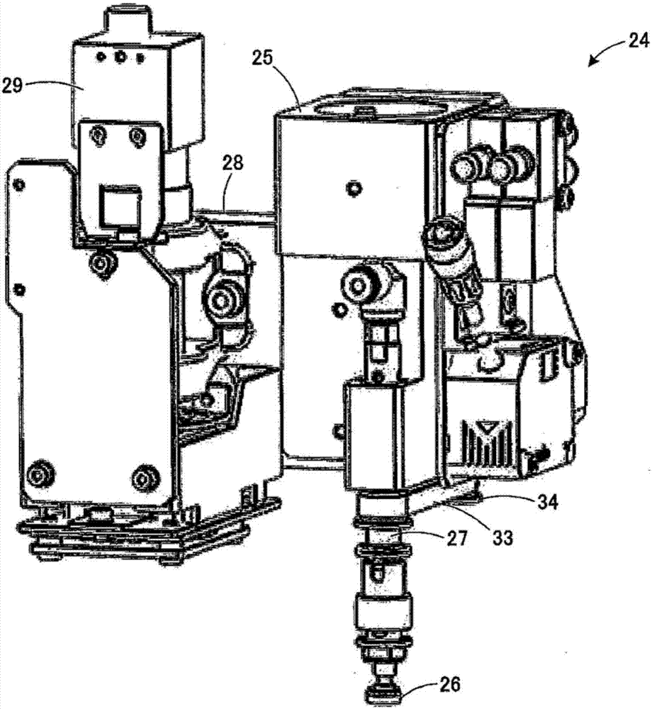
[0043] Next, the mounting device of this embodiment will be described with reference to the drawings. figure 1 It is a perspective view of the whole mounting device of this embodiment. figure 2 It is a perspective view of the mounting head of the mounting device of this embodiment. In addition, the attachment device of this embodiment is just an example, and can be changed suitably.

[0044] Such as figure 1 As shown, the mounting device 1 is configured to mount components supplied from various feeders (supply devices) 15A to 15C on the mounting surface of the substrate W by the vertical articulated robot 20 . On the base 10 of the mounting device 1 is arranged a transport unit 11 that transports the substrate W toward the work area in front of the vertical articulated robot 20 . The conveying unit 11 constitutes a conveying path by a pair of guide rails 12 that guide the conveyance of the substrate W and a pair of conveyer belts (not shown). The pair of conveyer belts sen...


PUM


Abstract

The invention provides an installation device for installing parts on a substrate, which is capable of improving the production beat through a simple and small device structure and installing variousparts with high precision through a vertical multi-joint robot. The installation device comprises a vertical multi-joint robot (20) for conveying parts to installation positions of a substrate from asupply device (15); a recognition unit (30) for recognizing the shapes of the parts in a conveying process through the vertical multi-joint robot; a first calculating portion (41) for calculating thedeviation amounts of the maintaining position of the vertical multi-joint robot relative to the parts according to the shapes of the parts; and a first correction portion (42) for correcting installation motions of the vertical multi-joint robot relative to the parts based on the deviation amounts of the maintaining position.

Description

technical field [0001] The present invention relates to a mounting device and a mounting method for mounting components on a substrate. Background technique [0002] Conventionally, as a mounting device, a mounting device having a gantry-type conveyance mechanism that moves a mounting head in the X direction and the Y direction is known. In this type of mounting apparatus, the component is picked up from the feeder by the suction nozzle, moved above the substrate, and the component is mounted by lowering the suction nozzle to the mounting point of the substrate. In the mounting apparatus as described above, it is difficult to mount special components such as leaded components on the board, and are usually mounted on the board by manual work. Therefore, installation errors such as wrong polarity and direction of components occur, and the working time varies depending on the force of the operator. [0003] It is also conceivable to assemble an articulated robot to a mounting...

Claims


Application Information

Patent Timeline
Patent Type & Authority Applications(China)
IPC IPC(8): H05K13/04H05K13/08
CPCH05K13/0408H05K13/043H05K13/0495H05K13/08
Inventor 土田阳介松田和弥藤田高史
Owner JUKI CORP
Why Eureka
Try Eureka