Magnetic positioning pendant of stone curtain wall capable of being replaced independently

A stone curtain wall and magnetic positioning technology, applied in the direction of walls, building components, covering/lining, etc., can solve the problems of elastic impact of spring leaf, T-shaped pendant stuck, difficult to repair, etc., to achieve easy production, free positioning, The effect of convenient processing

Pending Publication Date: 2018-05-01
CHONGQING IND POLYTECHNIC COLLEGE
View PDF10 Cites 3 Cited by
  • Summary
  • Abstract
  • Description
  • Claims
  • Application Information

AI Technical Summary

Problems solved by technology

Since the bottom of the stone veneer needs to be supported and stuck by the pre-fixed T-shaped pendant, this method can only be installed one by one from bottom to top. After the installation is completed, if the middle panel is damaged, it is very difficult to repair
Even if the repaired stone veneer is difficult to be stuck by the pre-fixed T-shaped pendant, there is a serious safety hazard
[0003] The patent originally designed by the applicant "A positioning structure for stone decorative panels used with push-in positioning pendants" (Patent No. 2015200227320) fixes the positioning corner blocks on the main body of the pendant and uses spring sheets. If the stone is damaged, The elastic force of the spring sheet may be affected, and when the stone is processed, the added groove must be larger than the thickness of the positioning corner block, and the position of the spring and the positioning nail must be left. If the spring is rusted, it will have a visible hidden safety hazard

Method used


Image

  • Magnetic positioning pendant of stone curtain wall capable of being replaced independently
  • Magnetic positioning pendant of stone curtain wall capable of being replaced independently
  • Magnetic positioning pendant of stone curtain wall capable of being replaced independently

Examples


Embodiment Construction

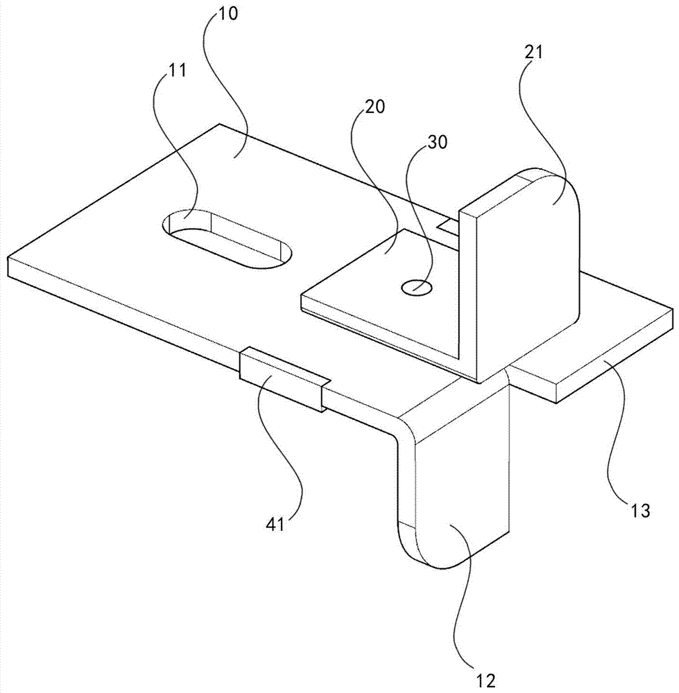
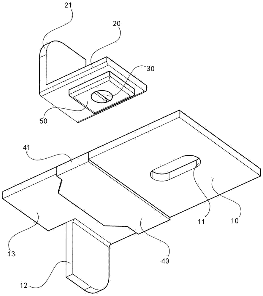
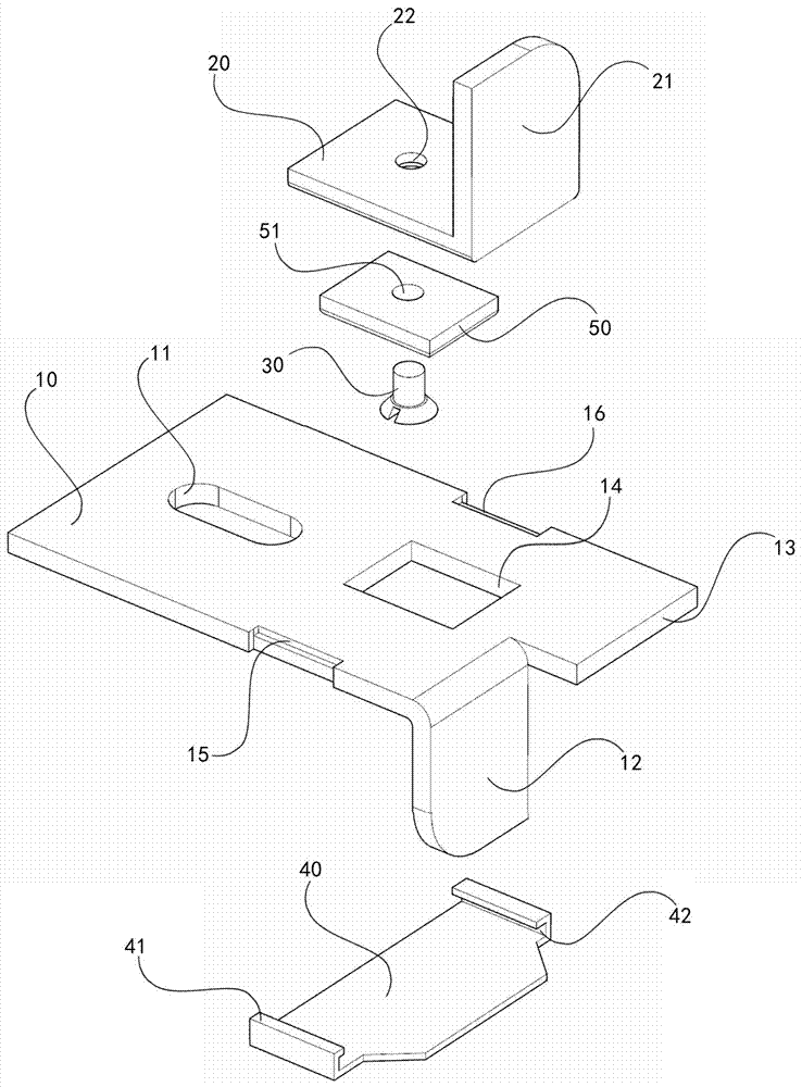
[0012] Below, in conjunction with accompanying drawing and embodiment, the present invention is further described: as Figure 1 to Figure 3 As shown in the figure, a separately replaceable magnetic positioning pendant for stone curtain wall includes a pendant main body 10, a positioning corner block 20, a screw 30, a steel sheet 40, and a magnet block 50; it is characterized in that the pendant main body 10 is provided with positioning Adjusting hole 11, downward hook head 12, load-bearing bar 13, square hole 14 of the main body of the pendant and positioning groove 15; the positioning groove 15 is provided with a positioning protrusion 16; the positioning corner block 20 is provided with upward hook head 21 and The screw hole 22; the screw 30 is screwed into the screw hole 22 through the circular hole 51 provided on the magnet block 50 to fix the magnet block 50 and the positioning corner block 20 together; the two sides of the steel sheet 40 are provided with square Hook 41,...


PUM


Abstract

The invention relates to a magnetic positioning pendant of a stone curtain wall capable of being replaced independently. The pendant comprises a pendant main body, a steel sheet, a positioning angle block and a magnet block, wherein the pendant is characterized in that a positioning adjusting hole, a downward hook head, a bearing strip and a pendant main body square hole are formed in the pendantmain body; square hooks which are internally square-groove-shaped are arranged on two sides of the steel sheet; an upward hook head is arranged at the front end of the positioning angle block and a positioning angle block square hole is formed in the middle; the magnet block is fixed in the positioning angle block square hole; part of the magnet block protrudes below the positioning angle block; length and width of the part, protruding out of the positioning angle block, of the magnet block are matched with those of the pendant main body square hole; the lower portion, protruding out of the positioning angle block, of the magnet block can be placed in the pendant main body square hole, and the thickness of the part, protruding below the positioning angle block, of the magnet block is consistent to that of the pendant main body. By adopting the magnetic positioning pendant, the positioning angle block can be fixed more steadily on the pendant main body.

Description

technical field [0001] The invention relates to a building exterior wall pendant, in particular to a separately replaceable magnetic positioning pendant for a stone curtain wall. Background technique [0002] At present, most of the stone veneer panels are hung on buildings by the dry-hanging method of steel frame. This method is to use T-shaped pendants to respectively embed the grooves of the upper and lower adjacent stone veneer panels and fix them with adhesive. Since the bottom of the stone veneer needs to be supported and stuck by the pre-fixed T-shaped pendant, this method can only be installed one by one from bottom to top. After the installation is completed, if the middle panel is damaged, it is very difficult to repair. Even the repaired stone veneer is difficult to be stuck by the pre-fixed T-shaped pendant, so there is a serious safety hazard. [0003] The applicant's original patent "A Positioning Structure of Stone Decorative Panel Used with Push-In Positioni...

Claims


Application Information

Patent Timeline
Patent Type & Authority Applications(China)
IPC IPC(8): E04B2/88E04F13/14E04F13/30
CPCE04B2/88E04F13/0883E04F13/14
Inventor 欧阳刚苏涛
Owner CHONGQING IND POLYTECHNIC COLLEGE
Why Eureka
Try Eureka