Well network structure for extra-heavy oil reservoir and oil extraction method

A technology for ultra-heavy oil and oil oil, which is applied in the direction of production fluid, earthwork drilling and production, wellbore/well components, etc. It can solve the problem that the oil drainage channel cannot be formed in the injection-production well, affects the recovery of crude oil in the upper part of the oil layer, and expands the steam flooding. Volume and other issues, to achieve the effect of improving oil recovery rate and oil recovery, simple and clear operation principle, and increasing exposed area

Active Publication Date: 2018-05-01
PETROCHINA CO LTD
View PDF7 Cites 10 Cited by
  • Summary
  • Abstract
  • Description
  • Claims
  • Application Information

AI Technical Summary

Problems solved by technology

In response to this contradiction, the main measure at present is to use vertical wells to assist steam injection in the upper part of the oil layer. Although this method can form a new steam cavity in the upper part of the interlayer, so that the crude oil in the upper oil layer has a certain fluidity, but due to the Located at the bottom of the oil layer, even if the temperature between the wells rises, it still cannot form an effective oil drainage channel between the injection and production wells, affecting the recovery of crude oil in the upper part of the oil layer
[0004] In the multi-lateral fishbone horizontal well currently used, the branch wellbore is often located in the same oil layer, and each branch is on the same plane. Although this method increases the exposed area of ​​the oil layer on the plane and expands the swept volume of steam flooding, the production increase effect is obvious; but Cannot give full play to the vertical advantages, realize the three-dimensional control of injection-production parameters, and alleviate the impact of formation heterogeneity on production effect

Method used


Image

  • Well network structure for extra-heavy oil reservoir and oil extraction method
  • Well network structure for extra-heavy oil reservoir and oil extraction method

Examples


Embodiment Construction

[0029] The details of the present invention can be understood more clearly with reference to the accompanying drawings and the description of specific embodiments of the present invention. However, the specific embodiments of the present invention described here are only for the purpose of explaining the present invention, and should not be construed as limiting the present invention in any way. Under the teaching of the present invention, the skilled person can conceive any possible modification based on the present invention, and these should be regarded as belonging to the scope of the present invention.

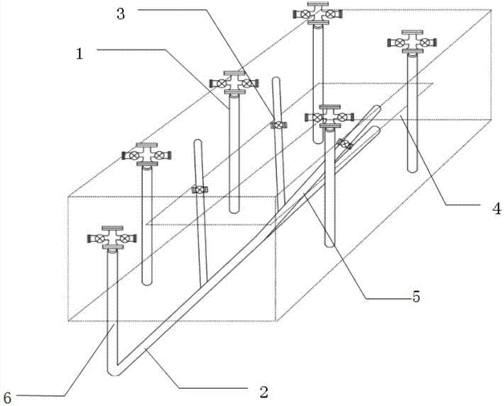
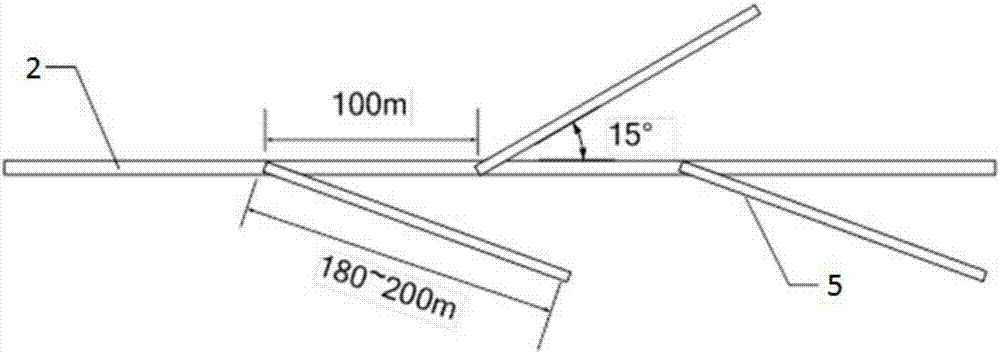
[0030] refer to figure 1 As shown, the present application discloses a steam flooding well pattern structure for super-heavy oil reservoirs, including: a fishbone horizontal well, including a vertical section 6, communicating with the lower end of the vertical section 6 and located below the interlayer 4 The horizontal section 2, a plurality of branch sections 5, one end...


PUM


Abstract

The invention discloses a steam-flooding well network structure for an extra-heavy oil reservoir and an oil extraction method. The well network structure comprises a herringbone horizontal well, at least one straight well and layered steam injection mechanisms. The herringbone horizontal well comprises a vertical section, a horizontal section communicating with the lower end of the vertical section and located on the lower portion of an interlayer, and a plurality of branch sections; one ends of the branch sections communicate with the horizontal section, and the other end of at least one of the branch sections is located above the interlayer; sectioned plugging devices are arranged in the positions, in the interlayer, of the branch sections; the herringbone horizontal well serves as an oil extraction well; the straight wells are arranged close to the horizontal section, serve as steam injection wells and are provided with at least two perforations located on the upper portion and thelower portion of the interlayer correspondingly; and the layered steam injection mechanisms are arranged in the straight wells and enable the perforations to be opened in a perforated mode. Accordingto the steam-flooding well network structure for the extra-heavy oil reservoir and the oil extraction method, the influence of formation heterogeneity on the production effect is avoided, the oil extraction speed and the crude oil recovery ratio are increased, and comprehensive benefits of heavy oil extraction are improved further.

Description

technical field [0001] The invention relates to the field of petroleum development, in particular to a well pattern structure and an oil recovery method for super heavy oil reservoirs. Background technique [0002] Super-heavy crude oil has a high viscosity, and the viscosity of degassed crude oil is greater than 50000mPa·s at the reservoir temperature. The method of combined steam flooding of vertical well and horizontal well is that the vertical steam injection well continuously injects high-dryness steam into the oil layer, and the heat carried by the steam continuously heats the oil layer, thereby greatly reducing the viscosity of the formation crude oil. The injected steam turns into hot fluid in the formation, and drives the crude oil to the periphery of the horizontal well production well at the bottom of the oil formation, and is extracted to the surface. In order to improve the recovery degree of the steam flooding stage, in the steam flooding stage, the thermal co...

Claims


Application Information

Patent Timeline
Patent Type & Authority Applications(China)
IPC IPC(8): E21B43/24E21B43/14
CPCE21B43/14E21B43/24
Inventor 周游刘彤张忠义李秀峦席长丰杜宣齐宗耀
Owner PETROCHINA CO LTD
Why Eureka
Try Eureka