
Automobile exhaust tube connecting device

An automobile exhaust and pipe connection technology, which is applied in the field of auto parts, can solve problems such as loud noise and severe vibration of the whole vehicle, and achieve the effects of ensuring shock absorption, uniform force, and reliability

Inactive Publication Date: 2018-05-01
浙江邝记汽车零部件有限公司
View PDF4 Cites 0 Cited by
  • Summary
  • Abstract
  • Description
  • Claims
  • Application Information

AI Technical Summary

Problems solved by technology

[0002] One end of the car exhaust pipe is connected to the car engine, and the other end is connected to the car chassis. The car engine will generate powerful vibrations while providing power for the car. If the vibration of the engine is not processed and transmitted to the car body through the exhaust pipe, it will The whole vehicle vibrates violently, and the existing exhaust pipe and connecting parts are made of metal materials, so the shaking of the exhaust pipe and the collision of the connecting parts will generate a lot of noise

Method used


Image

  • Automobile exhaust tube connecting device
  • Automobile exhaust tube connecting device
  • Automobile exhaust tube connecting device

Examples


Embodiment 1

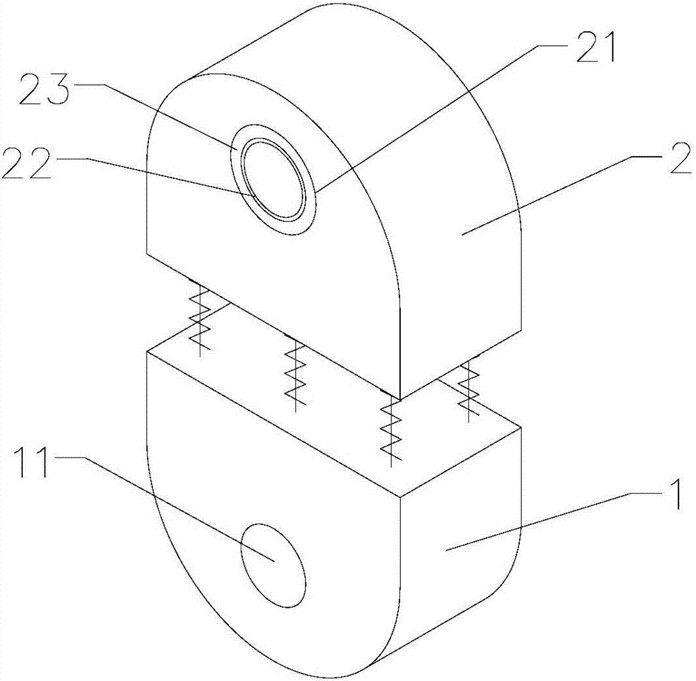
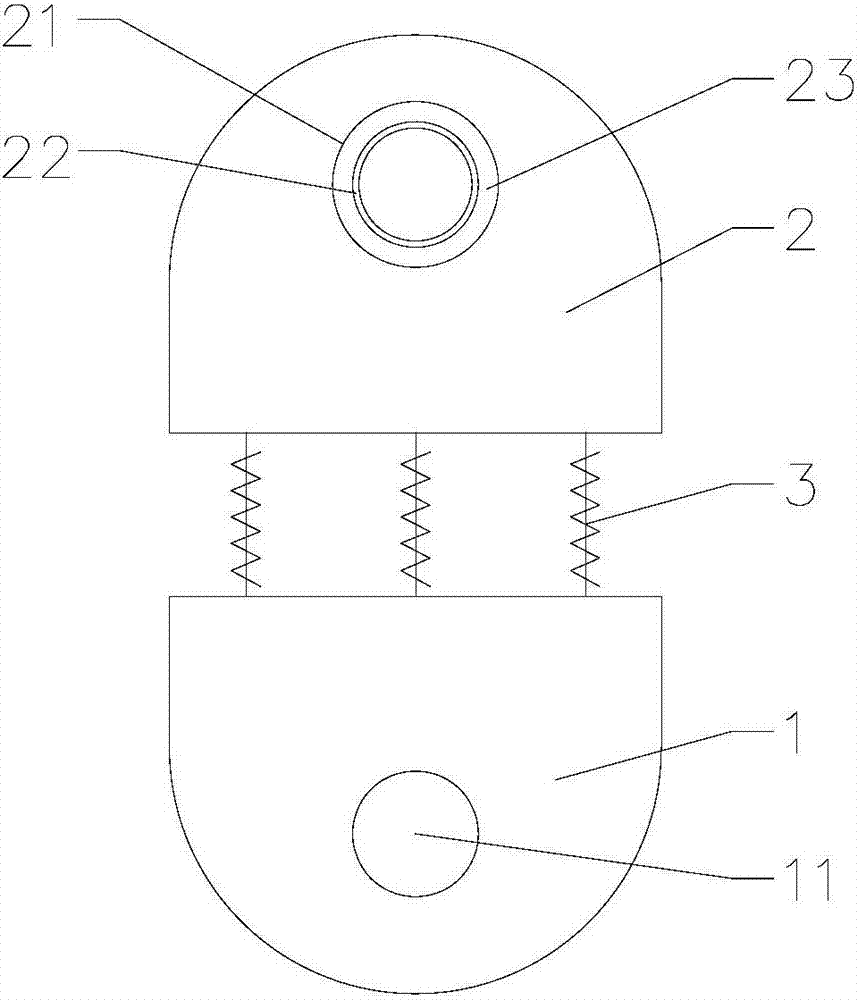
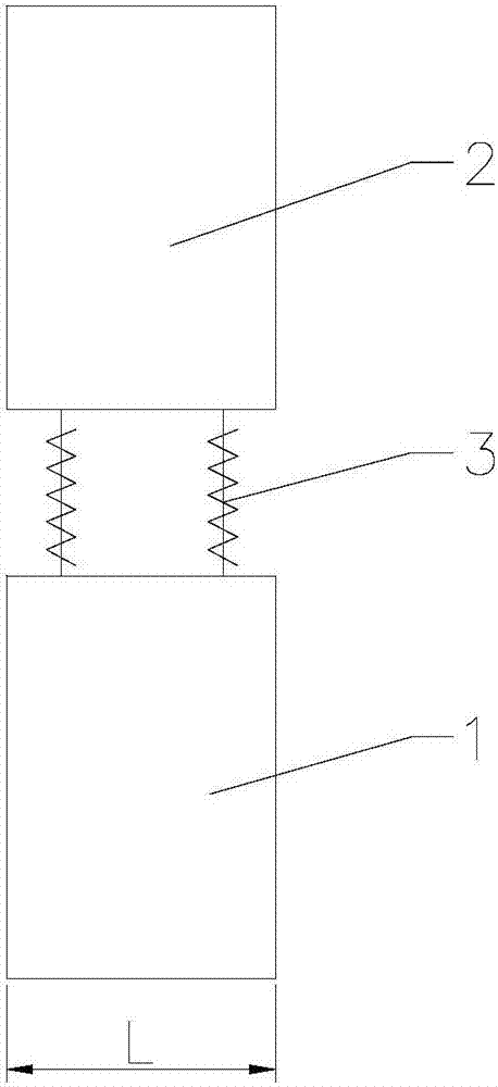
[0025] Such as Figure 1 to 3 As shown, the present invention provides an automobile exhaust pipe connecting device, which includes a fixing portion 1 and a connecting portion 2 arranged above the fixing portion 1. The fixing portion 1 is provided with a fixing hole 11 for fixed connection with the automobile chassis, and the connecting portion 2 A connecting hole 21 is provided. The connecting part 2 and the fixed part 1 are connected by a spring 3. The spring 3 provides elasticity, which acts as a shock absorber when the exhaust pipe vibrates, preventing the exhaust pipe from transmitting the vibration to the car chassis; connecting hole 21 There is a rubber collar 22 matched with the exhaust pipe. The exhaust pipe and the connecting part 2 are connected by the rubber collar 22. When the exhaust pipe collides with the rubber collar 22, it will not produce too much noise. To the effect of noise reduction; a shock absorber 23 is arranged between the rubber collar 22 and the con...

Embodiment 2

[0034] Such as Figure 4 As shown, the main difference between this embodiment and the first embodiment is that there are two fixing holes 11. There are two fixing holes 11, and the distance between the two fixing holes 11 and the connecting hole 21 is equal. The advantage of this arrangement is that the two fixing holes 11 can ensure the reliability of the connection between the automobile exhaust pipe connecting device and the automobile chassis, and the distance between the two fixing holes 11 and the connecting hole 21 is equal, so that the two fixing holes 11 An isosceles triangle is formed between the connecting hole 21 and the connecting hole 21, so that the force of the entire automobile exhaust pipe connecting device is more uniform, thereby ensuring the shock absorption effect of the automobile exhaust pipe connecting device.


PUM


Abstract

The invention provides an automobile exhaust tube connecting device. The automobile exhaust tube connecting device comprises a fixed part and a connecting part arranged above the fixed part, wherein afixing hole fixedly connected with an automobile chassis is formed in the fixed part; and the connecting part is equipped with a connecting hole. The automobile exhaust tube connecting device is characterized in that the connecting part is connected with the fixed part through the spring which provides elastic force to achieve the damping effect when the air exhaust tube vibrates, so that the airexhaust tube is prevented from transmitting vibrations to the automobile chassis; a rubber sleeve ring matched with the air exhaust tube is arranged in the connecting hole; during vibrations, the airexhaust tube and the rubber sleeve ring generate collision without generating too great noises, so that the noise reduction effect is achieved; and a damping part is arranged between the rubber sleeve ring and the connecting hole to further damp the air exhaust tube, so that vibrations of an engine are not transmitted to the automobile chassis through the air exhaust tube.

Description

Technical field [0001] The invention relates to the technical field of automobile parts, and in particular to an automobile exhaust pipe connecting device. Background technique [0002] One end of the car exhaust pipe is connected to the car engine, and the other end is connected to the car chassis. The car engine will generate strong vibrations while providing power to the car. If the vibration of the engine is transmitted to the car body through the exhaust pipe without treatment, it will The entire vehicle vibrates violently, and the existing exhaust pipes and connectors are all made of metal materials. The shaking of the exhaust pipe and the collision of the connectors will generate louder noise. Summary of the invention [0003] The purpose of the present invention is to provide a shock-absorbing and sound-absorbing automobile exhaust pipe connecting device. [0004] In order to achieve the above objective, the present invention adopts the following technical solutions: an aut...

Claims


Application Information

Patent Timeline
Patent Type & Authority Applications(China)
IPC IPC(8): F01N13/18
CPCF01N13/1811F01N13/1838
Inventor 夏聆纬赵春贤陆慧玲
Owner 浙江邝记汽车零部件有限公司
Learn More