Method for optimizing quantum circuit simulation

A circuit simulation and sub-circuit technology, applied in the field of quantum computing, can solve problems such as large storage space requirements, inability to calculate calculation time, and inappropriate simulation of quantum circuits, so as to achieve the effect of reducing storage space, calculation amount and storage space

Active Publication Date: 2018-05-01
ORIGIN QUANTUM COMPUTING TECH (HEFEI) CO LTD
View PDF4 Cites 10 Cited by
  • Summary
  • Abstract
  • Description
  • Claims
  • Application Information

AI Technical Summary

Problems solved by technology

[0005] Aiming at the problem in the prior art of calculating all the quantum states in the quantum circuit, the demand for storage space is too large to make the calculation impossible or the storage space is sufficient but the calculation time is too long to simulate the quantum circuit, the present invention provides a low calculation and low storage The simulation algorithm simulates the quantum circuit, that is, before simulating the quantum circuit, the quantum circuit is simplified and divided into blocks

Method used


Image

  • Method for optimizing quantum circuit simulation
  • Method for optimizing quantum circuit simulation
  • Method for optimizing quantum circuit simulation

Examples


Embodiment 1

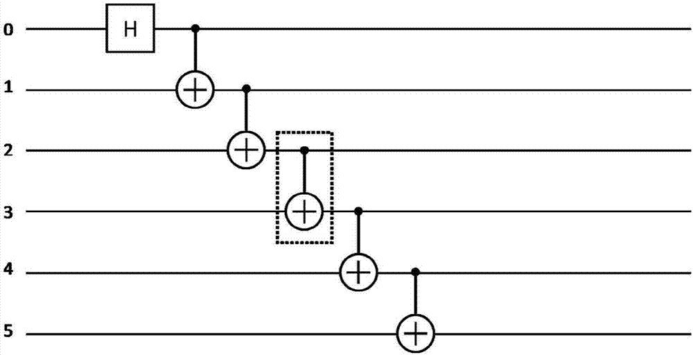
[0081] The quantum circuit shown in Figure 1(a) is simulated. In the dotted box is the CNOT gate to be transformed.

[0082] This circuit contains a total of 6 qubits and 6 quantum logic gates. Using the traditional method, the amount of computation and storage space required are

[0083] Cost(Legacy)=6*2 6 =384

[0084] Space (Legacy) = 2 6 =64

[0085] The following uses this scheme to simulate the circuit.

[0086] Execute step 1, and the input is the line to be simulated.

[0087] Execute step 2, set the threshold value to 3 bits, and the setting of the threshold value here is artificially controlled for the convenience of expressing the method. Because the circuit contains 6 qubits in total, and there is no two-quantum logic gate connection between any no more than 3 qubits and other qubits, go to step 3.

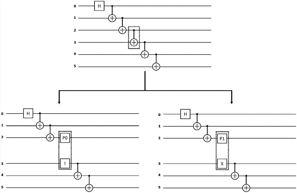
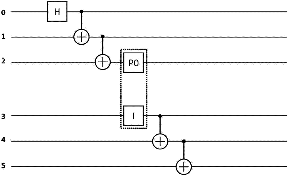
[0088] Execute step 3 to convert the circuit, and the target of the conversion is the logic gate (control NOT gate CNOT) inside the dotted box as shown in the ...

Embodiment 2

[0099] As shown in the quantum circuit simulation in Fig. 3(a), in the dotted box are two CZ gates to be converted in the following implementation process. This circuit contains a total of 8 qubits and 23 quantum logic gates. Using the traditional method, the amount of computation and storage space required are

[0100] Cost(Legacy)=14*2 8 =3854

[0101] Space (Legacy) = 2 8 =256

[0102] The following uses this scheme to simulate the circuit.

[0103]Execute step 1, and the input is the line to be simulated.

[0104] Execute step 2, set the threshold value to 4 bits, the setting of the threshold value here is artificially controlled, and the purpose is to express the method conveniently. Because the circuit contains 8 qubits in total, and there is no independent sub-circuit with qubits less than or equal to 4, go to step 3.

[0105] Execute step 3 to transform the circuit. The target of the transformation is the logic gate (control gate Z, CZ) inside the two dashed box...

Embodiment 3

[0119] The quantum circuit simulation shown in Figure 5(a) contains 6 qubits and 10 quantum logic gates in total. Using the traditional method, the amount of computation and storage space required are

[0120] Cost(Legacy)=10*2 6 =640

[0121] Space (Legacy) = 2 6 =64

[0122] The following uses this scheme to simulate the circuit.

[0123] Execute step 1, and the input is the line to be simulated.

[0124] Execute step 2, set the threshold value to 3 bits, and the setting of the threshold value here is artificially controlled for the convenience of expressing the method. Because the circuit contains 6 qubits in total, and there is no two-quantum logic gate connection between any no more than 3 qubits and other qubits, go to step 3.

[0125] Execute step 3, transform the circuit, and the target of the transformation is the TOFFOLI gate in the dotted box as shown in the figure (that is, the N=3 quantum controlled NOT gate). According to Theorem 2, the 3-bit quantum contr...


PUM


Abstract

The invention discloses a method for optimizing quantum circuit simulation and belongs to the field of quantum computation. The method for optimizing the quantum circuit simulation comprises the following steps: (1) transforming an N-bit quantum logical gate into M groups quantum logical gates, wherein a simulation result is the sum of results of simulation carried out on M groups transformed circuits respectively, N is more than or equal to 2, and M is more than or equal to 2; and (2) continuing transforming the N-bit quantum logical door in a subcircuit after transformation every time untilan independent subcircuit is found out, and carrying out simulation on each independent subcircuit. Compared with the prior art, the method disclosed by the invention overcomes the technical problemsthat quantum circuit simulation storage space is too large and computation time is too long. The method disclosed by the invention can carry out simulation on a quantum circuit by virtue of a simulation algorithm with low calculated amount and low storage and has the advantages of increasing computing speed of a computer, reducing storage space and improving bit quantity limit of a classical computer simulation quantum circuit.

Description

technical field [0001] The invention belongs to the field of quantum computing, and more specifically relates to a method for optimizing a quantum computer simulation system. Background technique [0002] The quantum algorithm described by the quantum circuit model is a method of manipulating a quantum computer to process the input state and output a specific measurement value. When running quantum algorithms, quantum computers have the ability to deal with mathematical problems more efficiently than ordinary computers (for example, they can accelerate the time to crack RSA keys from hundreds of years to hours), so they have become a key technology under research. technology. The processing speed of quantum computers increases exponentially with the number of qubits. It is expected that when the number of qubits exceeds 50, the processing speed of quantum computers on specific problems will be faster than the sum of the processing speeds of all supercomputers in the world. ...

Claims


Application Information

Patent Timeline
Patent Type & Authority Applications(China)
IPC IPC(8): G06F17/50
CPCG06F30/20
Inventor 朱美珍杨夏
Owner ORIGIN QUANTUM COMPUTING TECH (HEFEI) CO LTD
Why Eureka
Try Eureka