Intelligent in-situ recognition system and method for electronic fence based on image matching

A technology of electronic fence and recognition system, which is applied in image enhancement, image analysis, image data processing, etc., can solve problems such as being unable to correctly identify targets, and achieve the effect of saving financial resources

Inactive Publication Date: 2018-05-01
SHANGHAI INST OF TECHNICAL PHYSICS - CHINESE ACAD OF SCI
View PDF5 Cites 10 Cited by
  • Summary
  • Abstract
  • Description
  • Claims
  • Application Information

AI Technical Summary

Problems solved by technology

Many systems can no longer correctly identify the target when

Method used


Image

  • Intelligent in-situ recognition system and method for electronic fence based on image matching
  • Intelligent in-situ recognition system and method for electronic fence based on image matching
  • Intelligent in-situ recognition system and method for electronic fence based on image matching

Examples


Embodiment Construction

[0052] Embodiments of the present invention will be described below in conjunction with the accompanying drawings.

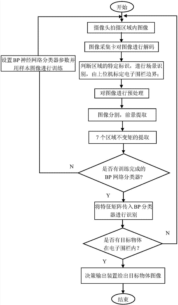
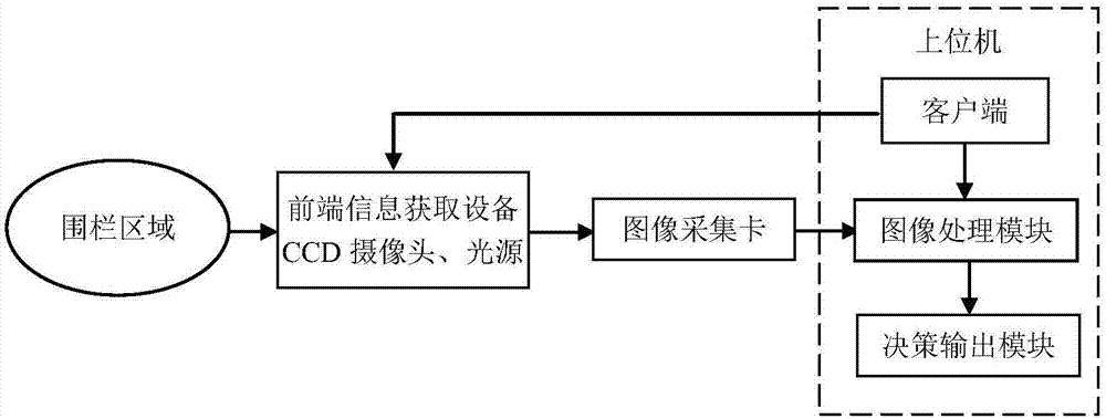
[0053] Such as figure 1 It is a flow chart of the electronic fence identification system of the present invention, such as figure 2 It is a system diagram according to an embodiment of the present invention, an image-matching-based intelligent on-site recognition system and recognition method for electronic fences, which is suitable for various target recognition in various scenarios, especially for mass-produced parts or assembly lines target object recognition. The electronic fence is a virtual electronic fence, and the electronic fence identification system includes a front-end detection device 1 , an image acquisition card 2 and a host computer 3 .

[0054] The front-end detection equipment includes a CCD camera and a light source. The surface to be tested is a wide, continuous surface with a single color, which requires continuous, online, and high-speed...


PUM


Abstract

The invention discloses an intelligent in-situ recognition system and method for an electronic fence based on image matching. The system comprises front end information obtaining equipment, an image collection card, and an upper computer. The front end information obtaining equipment comprises a CCD camera and a light source, and is connected to the image collection card. The image collection cardis connected with the upper computer. The upper computer comprises a client, an image processing module, and a decision output module. The client is connected to the image processing module, and is connected with the CCD camera. The image processing module outputs data to the decision output module. The system is based on a Hu invariant moment and an improved BP neural network, and carries out the in-situ recognition of an object based on the morphological characteristic matching. The image processing module carries out the determining of the electronic fence, the image processing, the extraction of the Hu invariant moment and the training of the BP neural network, and a maturely trained BP classifier is used for the in-situ classification and recognition of the object, and outputs a result to the decision output module. The system is simple in structure, is suitable for most of scenes, and can achieve the quick in-situ recognition of the object in the electronic fence.

Description

technical field [0001] The invention relates to the field of electronic fence monitoring and computer image processing, in particular to an image-matching-based intelligent on-site recognition system and a recognition method for an electronic fence, which is suitable for object on-site classification and recognition in most scenarios. Background technique [0002] With the advancement of social science and technology, human production behaviors and lifestyles are also constantly developing and changing, new technologies and new products are constantly emerging, and a large number of life and production activities occur, making intelligent monitoring and identification systems increasingly required by people. The real-time monitoring of a specified area to ensure on-site safety or identify various activities in the monitored area is inseparable from the support of electronic fence technology. Traditional and common electronic fences generally use photoelectric sensors to form...

Claims


Application Information

Patent Timeline
IPC IPC(8): G08B13/12G08B13/196G06K9/00G06K9/20G06K9/32G06K9/46G06K9/62G06N3/08G06T7/12G06T7/194
CPCG06N3/084G06T7/12G06T7/194G08B13/124G08B13/19663G06T2207/30232G06V20/52G06V10/22G06V20/62G06V10/462G06F18/24
Inventor 张悦孙胜利
Owner SHANGHAI INST OF TECHNICAL PHYSICS - CHINESE ACAD OF SCI
Why Eureka
Try Eureka