Novel hybrid topology multifunctional power electronics distribution network device and control method

A hybrid topology, power electronics technology, applied in the power field, can solve the problems of low equipment usage, difficult detection, weak current signal, etc.

Pending Publication Date: 2018-05-01
重庆聚陆新能源有限公司
View PDF5 Cites 9 Cited by
  • Summary
  • Abstract
  • Description
  • Claims
  • Application Information

AI Technical Summary

Problems solved by technology

The signal injection method generally uses a signal injection device to inject a specific current signal into the system through the bus PT. Commonly used AC signal injection has problems such as being limited by the capacity of the PT and the current signal transmitted from the PT to the system is relatively weak and difficult to detect.
[0005] The above-mentioned methods of line-to-ground parameter measurement, single-phase ground arc suppression, and single-phase line ground point positioning not only have insurmountable shortcomings, but also require specific protection devices for each function, resulting in complicated protection devices for the distribution network system. Inconvenient management, low utilization rate of protection and detection devices, etc.
The flexible grounding device based on power electronic devices is generally installed at the neutral point of the distribution network, and only works when a single-phase ground fault occurs in the distribution network line, without other additional functions, and the equipment utilization rate is low

Method used


Image

  • Novel hybrid topology multifunctional power electronics distribution network device and control method
  • Novel hybrid topology multifunctional power electronics distribution network device and control method
  • Novel hybrid topology multifunctional power electronics distribution network device and control method

Examples


Embodiment Construction

[0039] The preferred embodiments of the present invention will be described in detail below in conjunction with the accompanying drawings; it should be understood that the preferred embodiments are only for illustrating the present invention, rather than limiting the protection scope of the present invention.

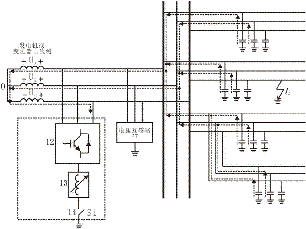
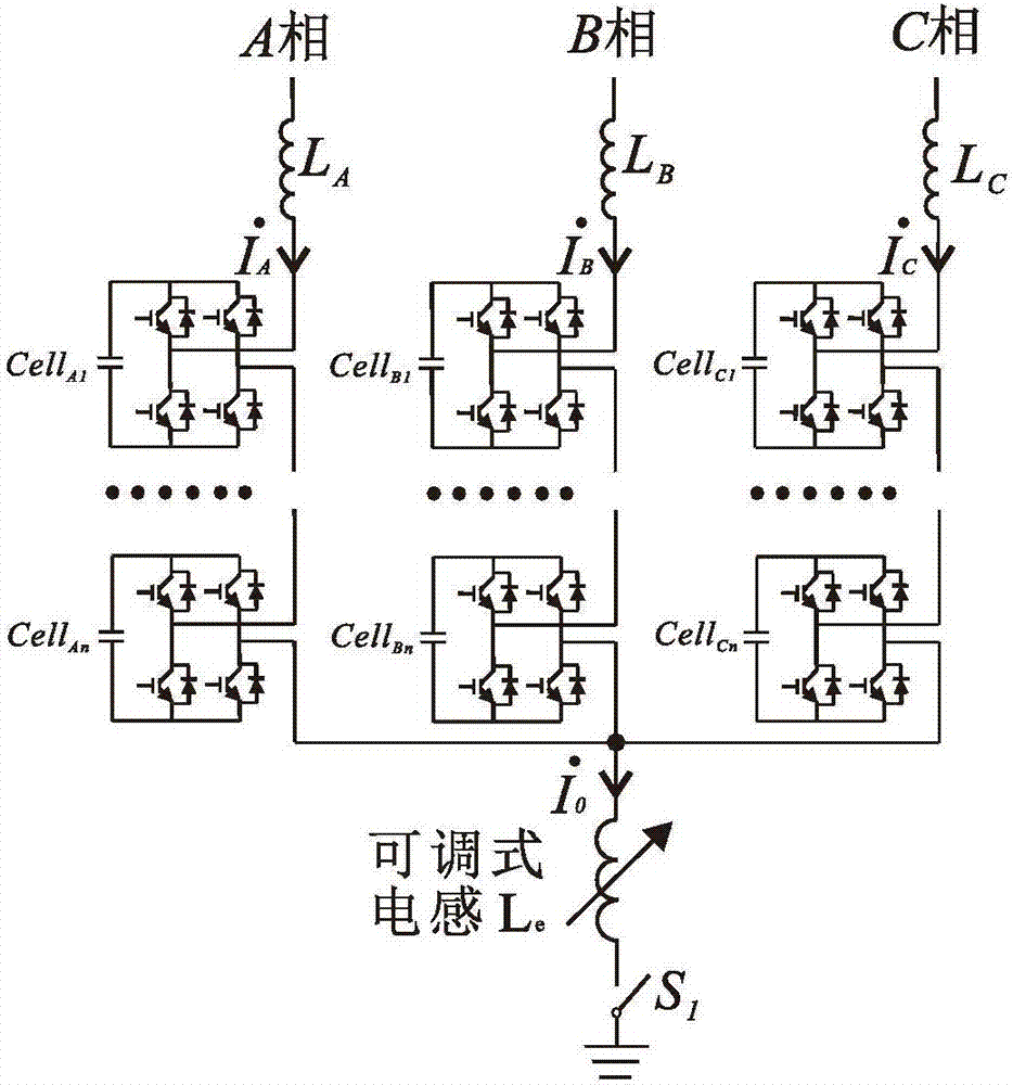
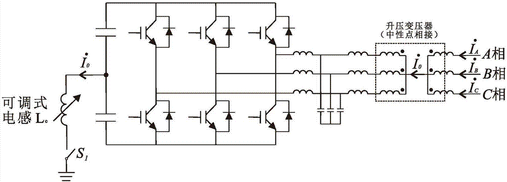
[0040] figure 1 It is the topological diagram of the distribution network and the structural diagram of the inventive device; figure 2 It is a schematic structural diagram of an inventive device with a cascaded H bridge as an embodiment; image 3 It is a structural schematic diagram of a multifunctional device with two-level inverter and step-up transformer as an embodiment; Figure 4 It is a control algorithm block diagram of the present invention; Figure 5 To measure the equivalent circuit of line-to-ground capacitance; Figure 6 Schematic diagram of the fault signature current detector layout for single-phase-to-earth fault location in distribution network.

[...


PUM


Abstract

The invention discloses a novel hybrid topology multifunctional power electronics distribution network device and a control method. The device is arranged on a generator side or a secondary side of adistribution network transformer or a bus-bar side of a distribution network. The device comprises a three-phase converter, an adjustable inductor and a controllable switch, wherein a neutral point ofthe three-phase converter can be ground by connecting the adjustable inductor and the controllable switch in series. During normal operation of the distribution network, the device works in a reactive compensation mode, the controllable switch is closed at fixed time to measure a circuit grounding parameter, and an inductive reactance value of the adjustable inductor is changed according to the circuit grounding parameter. The device disclosed by the invention has functions of reactive compensation, measurement of the circuit grounding parameter, single-phase grounding arc extinction of the circuit, single-phase grounding point route selection of the circuit and location, and the integrated design of multiple functions is realized. Moreover, the normal operation of the reactive compensation function of the device can be maintained while realizing the functions of measurement of the circuit grounding parameter, single-phase grounding arc extinction, single-phase grounding point route selection of the circuit and location, and the like.

Description

technical field [0001] The invention belongs to the electric power industry, and in particular relates to the fields of reactive power compensation of a distribution network of a three-phase neutral point ungrounded system, online measurement of line-to-ground parameters, single-phase ground fault arc suppression, and single-phase ground point positioning. Novel hybrid topology multifunctional power electronic distribution network device and control method. Background technique [0002] Most of the domestic medium-voltage distribution network adopts the operation mode of ungrounded neutral point. Due to the development of the city, the urban distribution network continues to expand, the use of power cables continues to increase, and the capacitance of the distribution line to the ground is increasing. When a single-phase ground fault occurs in the network, it is easy to cause serious ground current. The capacitive current of distribution network lines to ground is an import...

Claims


Application Information

Patent Timeline
Patent Type & Authority Applications(China)
IPC IPC(8): H02J3/18H02H9/08G01R31/08G01R31/02
CPCH02H9/08H02J3/1821G01R31/086G01R31/50Y02E40/30Y04S10/52
Inventor 周兴达陆帅王涛
Owner 重庆聚陆新能源有限公司
Why Eureka
Try Eureka