A driving circuit for lamp power control

A power control and lamp technology, applied in the direction of electric light sources, electrical components, light sources, etc., can solve the problems of circuit complexity, lower integration, increased production costs, etc. The effect of service life

Active Publication Date: 2019-12-13
SUZHOU RUIGUANG ELECTRONICS
View PDF9 Cites 0 Cited by
  • Summary
  • Abstract
  • Description
  • Claims
  • Application Information

AI Technical Summary

Problems solved by technology

However, the driving voltage generated by the MCU controlling the driving module of the existing driving technology can only drive one fluorescent tube
If multiple fluorescent tubes are driven, multiple MCU control modules and corresponding drive modules must be required, which will complicate the circuit, complicate the production process, reduce the integration level, and increase the production cost

Method used


Image

  • A driving circuit for lamp power control
  • A driving circuit for lamp power control
  • A driving circuit for lamp power control

Examples


Embodiment Construction

[0021] The present invention will be further described in detail below in conjunction with the accompanying drawings and embodiments. It should be understood that the specific embodiments described here are only used to explain the present invention, but not to limit the present invention. In addition, it should be noted that, for the convenience of description, only some structures related to the present invention are shown in the drawings but not all structures.

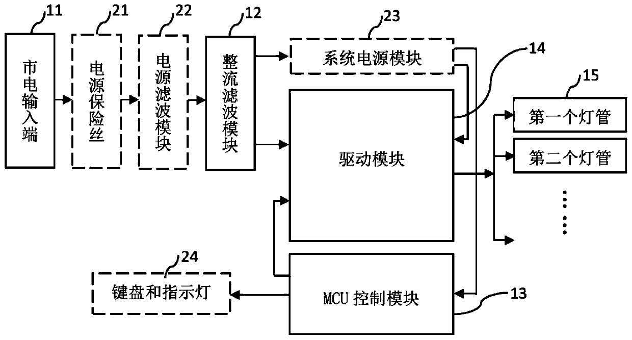
[0022] figure 1 A structural block diagram of a drive circuit for lamp power control provided by an embodiment of the present invention. Such as figure 1 As shown, the driving circuit includes: a mains power input terminal 11 , a rectification and filtering module 12 , an MCU control module 13 , a driving module 14 and at least two lamp tubes 15 .

[0023] Among them, the mains input terminal 11 is used to connect the mains to obtain the mains AC voltage; the rectification and filtering module 12 is connected to...


PUM


Abstract

The invention discloses a drive circuit for power control of lamp tubes. The circuit comprises an electric supply input end, a rectifier and filter module, an MCU control module, a drive module and atleast two lamp tubes, wherein the electric supply input end is used for being connected with electric supply to obtain AC voltage of the electric supply; the rectifier and filter module is connectedwith the electric supply input end and is used for converting the AC voltage of the electric supply into DC voltage; the MCU control module is used for outputting two control signals of lamp tube drive voltage; the control signals are used for controlling waveforms and frequencies of power voltage of driving the lamp tubes; the drive module is connected with the rectifier and filter module and theMCU control module separately and is used for converting the DC voltage output by the rectifier and filter module into the power voltage of driving the lamp tubes under the action of the control signals generated by the MCU control module; one pin of each lamp tube is connected with the drive module and the lamp tubes emit light under the drive of the power voltage, so that the condition that onedrive module drives a plurality of lamp tubes to emit light at the same time is achieved; and furthermore, the brightness of the lamp tubes can be freely adjusted, the drive circuit has a preheatingfunction and the life of the lamp tubes is prolonged.

Description

technical field [0001] Embodiments of the present invention relate to lamp tube driving technology, and in particular to a drive circuit for lamp power control. Background technique [0002] With the advancement and development of science and technology, phototherapy products have been favored by more and more people, and its light source generally adopts fluorescent tubes with high luminous efficiency. [0003] The driving methods of traditional fluorescent tubes are mainly divided into two categories, one is magnetic ballasts, and the other is electronic ballasts. Since these two types of ballasts both adopt the principle of mechanical oscillation, they have the defects of large volume, high cost, short life, low integration, and the inability to freely adjust the brightness of the lamp tube. [0004] At present, the driving method of the fluorescent tube is generally to utilize a Microcontroller Unit (MCU) to control a driving module to generate a voltage for driving the...

Claims


Application Information

Patent Timeline
Patent Type & Authority Patents(China)
IPC IPC(8): H05B41/26H05B41/36
CPCH05B41/26H05B41/36
Inventor 杨崇民龚坚康
Owner SUZHOU RUIGUANG ELECTRONICS
Why Eureka
Try Eureka