
Airflow preheating assembly applied to separation analysis instrument and application

A technology of separation analysis and airflow, which is applied to the parts of particle separator tubes, electrical components, particle separation tubes, etc., which can solve the problems of too simple airflow channels and low heat conduction efficiency of heating devices

Active Publication Date: 2021-06-18
DALIAN INST OF CHEM PHYSICS CHINESE ACAD OF SCI
View PDF11 Cites 0 Cited by
  • Summary
  • Abstract
  • Description
  • Claims
  • Application Information

AI Technical Summary

Problems solved by technology

[0005] An airflow preheating device invented by Chen Jiatai et al. (patent application number 201510233789.X), the invention provides an airflow preheating device, including an airflow channel, one end of the airflow channel is provided with an air inlet; the other end is provided with an outlet Air port; there is a heating device for heating the gas flowing in the air flow channel in the area of ​​the air flow channel; but the air flow channel used is too simple, and the heat conduction efficiency of the heating device is not high

Method used


Image

  • Airflow preheating assembly applied to separation analysis instrument and application
  • Airflow preheating assembly applied to separation analysis instrument and application
  • Airflow preheating assembly applied to separation analysis instrument and application

Examples


Embodiment 1

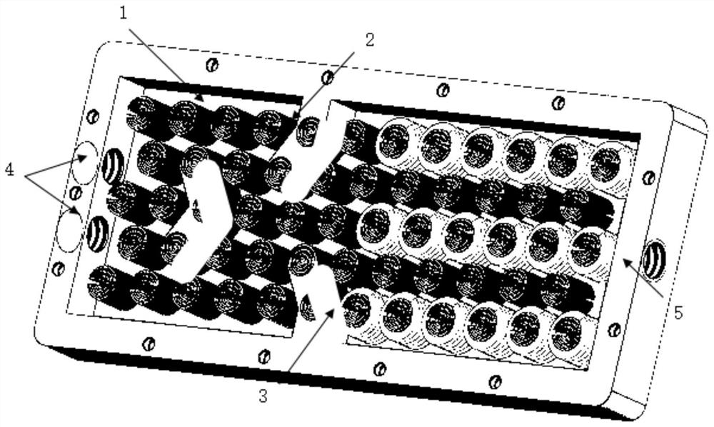
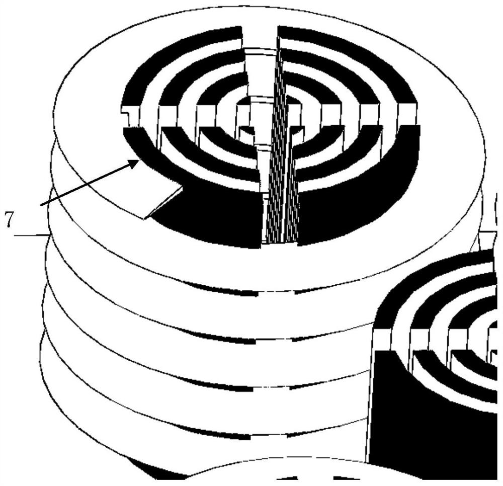
[0046] The columnar body in the airflow preheating component has both an axial contact area and a lateral diffusion area, and the cooling fins wrapped around it have the function of increasing the contact area and improving the heat conduction efficiency. Use thermal conductive silicone grease (thermal conductivity greater than 11W / (m.k)) on one side of the heating plate to fully contact the groove wall at the bottom of the cavity to remove excess air. Match the two threaded holes of [air inlet] with two quick-change joints (metal) of M3 / 5 / 6 specifications, lead out two PTFE hoses, and connect them with the gas outlet of the flow controllable gas generating device. The PTFE hose is connected by a Y-type 3-way quick-change adapter; match a threaded hole of the [air outlet] with a M3 / 5 / 6 quick-change joint (metal) to lead out a PTFE hose .

[0047] Set the heating temperature of the heating plate to 50°C, use a thermometer to measure the temperature of the airflow at the air in...

Embodiment 2

[0049] The columnar body in the airflow preheating component has both an axial contact area and a lateral diffusion area, and the cooling fins wrapped around it have the function of increasing the contact area and improving the heat conduction efficiency. Use thermal conductive silicone grease (thermal conductivity greater than 11W / (m.k)) on one side of the heating plate to fully contact the groove wall at the bottom of the cavity to remove excess air. Match the two threaded holes of [air inlet] with two quick-change joints (metal) of M3 / 5 / 6 specifications, lead out two PTFE hoses, and connect them with the gas outlet of the flow controllable gas generating device. The PTFE hose is connected by a Y-type 3-way quick-change adapter; match a threaded hole of the [air outlet] with a M3 / 5 / 6 quick-change joint (metal) to lead out a PTFE hose .

[0050] Set the heating temperature of the heating plate to 70°C, and use a thermometer to measure the airflow temperature at the outlet to...

Embodiment 3

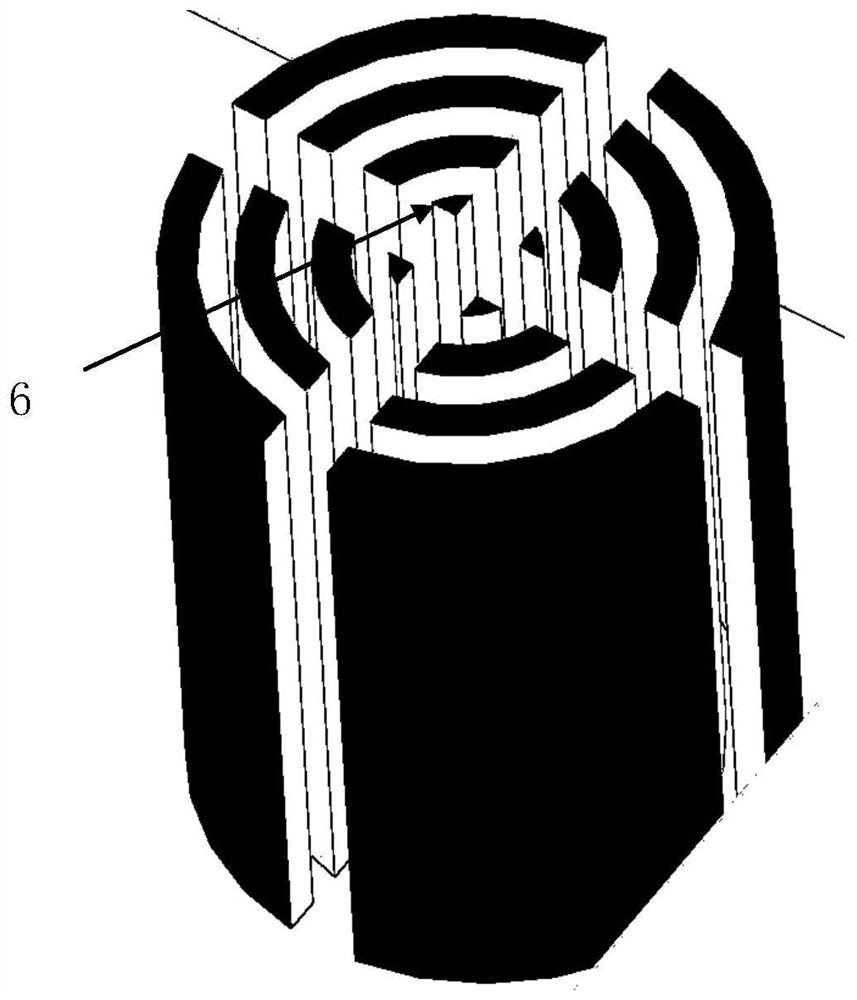
[0054] The upper and lower ends of each column in the airflow preheating assembly are provided with three ring-shaped through-holes that pass through in sequence, and two intersecting strip-shaped through-holes are opened between the upper and lower ends of the column, so that each column The body is composed of 4 gaps, 4 ring columns with diameters of 0.5mm, 1.5mm, 2.5mm, 3.5mm and a height of 5mm, and the wall thickness of the ring is 0.25mm, and the gap width is 0.2-0.3mm . The horizontal distance between adjacent columnar bodies is 6 mm, and the vertical distance is 5 mm. The heat sink is attached to the side wall of the columnar body, the pitch of the heat sink is 0.8-1 mm, the number of turns of the heat sink is 5-6 turns, and the starting angle is 50-90 degrees. Match the two threaded holes of [air inlet] with two quick-change joints (metal) of M3 / 5 / 6 specifications, lead out two PTFE hoses, and connect them with the gas outlet of the flow controllable gas generating d...


PUM


Abstract

The invention discloses an airflow preheating assembly applied to a separation analysis instrument. The airflow preheating assembly is composed of an integrated hollow sealed cavity, the interior of the sealed cavity is composed of three heat conduction assemblies in different structures, and the sealed cavity is divided into two drainage basins of different areas. Room-temperature air or clean air flow enters the buffer shunting area through two threaded holes (air inlets) in one side of the closed cavity, is preliminarily preheated by the columnar body, is naturally shunted by the diversion baffle plate, is injected into the component diffusion area, and flows out from a threaded hole (air outlet) in the other side of the cavity after making full contact and exchanging heat with the radiating fins on the side walls of the columnar body. The columnar body has an axial contact area and a transverse diffusion area, and the radiating fins wrapping the periphery of the columnar body can increase the contact area, thereby improving the heat conduction efficiency, ensuring that the airflow is heated to the expected temperature of the cavity, and realizing the function of preheating the airflow. The airflow preheating assembly is high in heat conduction efficiency, stable in flow, small in pressure loss, controllable in temperature and suitable for the preheating and separation analysis technology of air or clean gas.

Description

technical field [0001] The invention relates to the technical fields of precision machinery manufacturing, fluid mechanics, thermodynamics, etc., in particular to an air flow preheating component applied to a separation analysis instrument. Background technique [0002] Ion Mobility Spectrometry (IMS) technology is a separation, analysis and detection technology that appeared in the middle and late 20th century. Compared with traditional mass spectrometry and chromatographic analysis instruments, it has simple system, low detection limit, fast response speed, high stable features. It can detect trace substances in a normal pressure environment, and is suitable for real-time monitoring. Its working conditions are not vacuum conditions, but normal atmospheric pressure conditions. The overall airflow of the instrument is lower than 2ksccm, which is distributed and regulated by the airflow generating device, and the overall airflow is divided into "drift gas", "carrier gas", "r...

Claims


Application Information

Patent Timeline
Patent Type & Authority Applications(China)
IPC IPC(8): H01J49/04
CPCH01J49/0468H01J49/0422
Inventor 张远智李海洋王新蒋丹丹肖瑶
Owner DALIAN INST OF CHEM PHYSICS CHINESE ACAD OF SCI
Learn More