A method for synchronously forming lining rings of plate heat exchangers under axial pressure with constrained tubes

A technology of plate heat exchangers and heat exchangers, applied in the direction of metal processing equipment, etc., can solve problems affecting product quality, product appearance, and heat exchanger service life, so as to simplify the processing process, improve processing efficiency and form quality effect

Active Publication Date: 2019-10-29
XI AN JIAOTONG UNIV
View PDF8 Cites 0 Cited by
  • Summary
  • Abstract
  • Description
  • Claims
  • Application Information

AI Technical Summary

Problems solved by technology

The weld on the flange edge of the metal lining not only affects the appearance of the product, but also affects the quality of the product. Especially during service, the weld is prone to corrosion, which affects the service life of the heat exchanger and increases the difficulty of maintenance of the heat exchanger. The publication number is CN105945110A The Chinese invention patent proposed a device for simultaneous processing of flanges at both ends, which is essentially one-time stamping and flanging, and is only suitable for forming flanges with small sizes. If the size of the formed flange is large, it still needs Perform multi-pass stamping and flanging forming

Method used


Image

  • A method for synchronously forming lining rings of plate heat exchangers under axial pressure with constrained tubes
  • A method for synchronously forming lining rings of plate heat exchangers under axial pressure with constrained tubes
  • A method for synchronously forming lining rings of plate heat exchangers under axial pressure with constrained tubes

Examples


Embodiment 1

[0025] Embodiment 1: A method for synchronously forming the lining ring of a plate heat exchanger with constrained tube axial pressure, including the following steps:

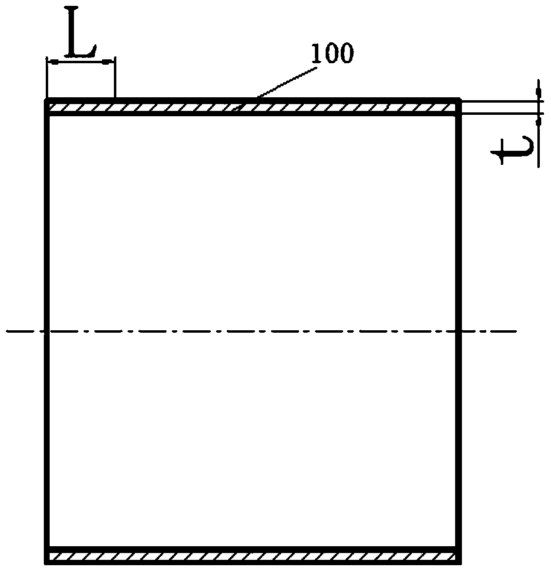
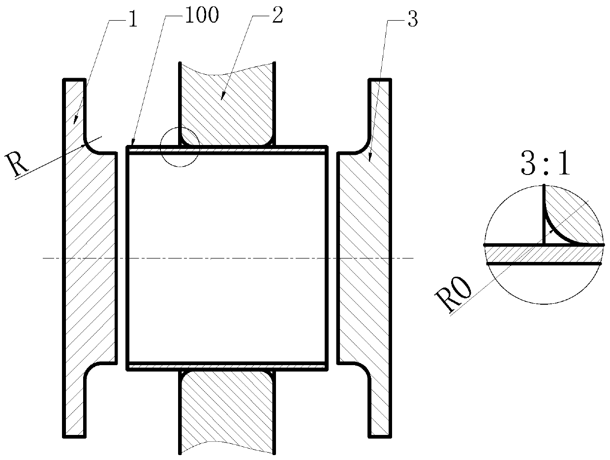
[0026] 1), refer to figure 1 and figure 2 , the pipe 100 is assembled in the inner hole of the plate heat exchanger 2, the fillet of the inner hole of the plate heat exchanger 2 is R0, the length of the free end of the pipe 100 is L, and the thickness is t, and the plate heat exchanger 2 is fixed, Ensure that the position of the pressure plate 2 of the plate heat exchanger is in the middle of the first tube axial pressure punch 1 and the second tube axial pressure punch 3, and constrain the outer wall of the pipe 100;

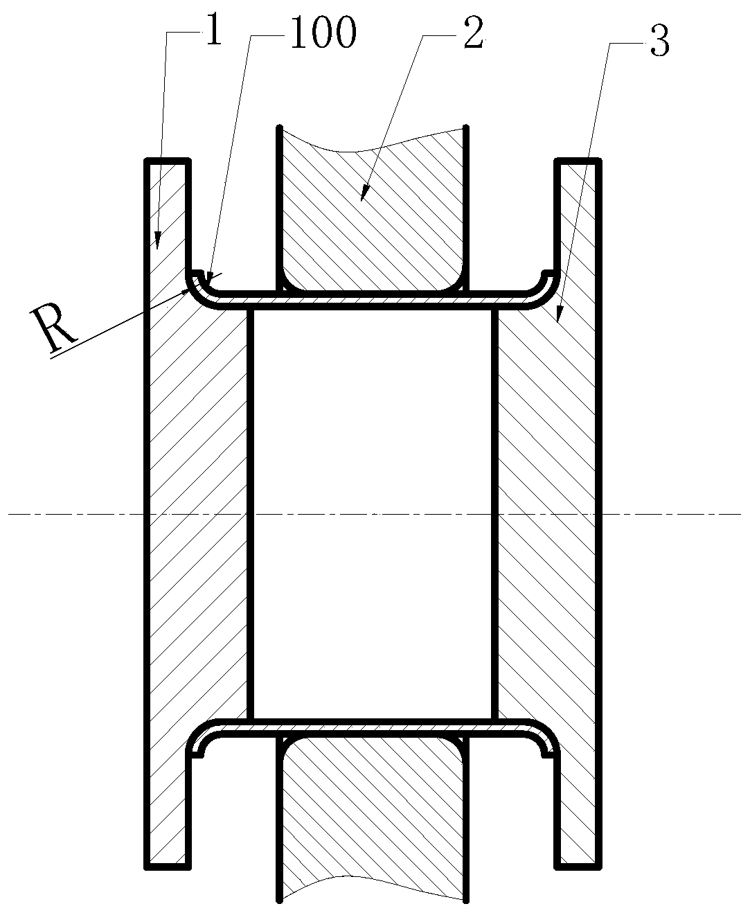
[0027] 2), refer to image 3 , the first tube axial pressing punch 1 and the second tube axial pressing punch 3 are fed towards each other along the axial direction at the same speed, and the free end of the pipe 100 is connected to the first tube axial pressing punch 1 and the second tube a...

Embodiment 2

[0031] Embodiment 2: A method for synchronously forming the lining ring of a plate heat exchanger with constrained tube axial pressure, including the following steps:

[0032] 1), refer to figure 1 and figure 2 , the pipe 100 is assembled in the inner hole of the plate heat exchanger 2, the fillet of the inner hole of the plate heat exchanger 2 is R0, the length of the free end of the pipe 100 is L, and the thickness is t, and the plate heat exchanger 2 is fixed, Ensure that the position of the pressure plate 2 of the plate heat exchanger is in the middle of the first tube axial pressure punch 1 and the second tube axial pressure punch 3, and constrain the outer wall of the pipe 100;

[0033] 2), refer to image 3 , the first tube axial pressing punch 1 and the second tube axial pressing punch 3 are fed towards each other along the axial direction at the same speed, and the free end of the pipe 100 is connected to the first tube axial pressing punch 1 and the second tube a...


PUM


Abstract

The invention relates to a method for synchronously forming a backing ring of a plate heat exchanger through constrained tube axial compression. The method comprises the steps of firstly assembling atubular product into an inner hole of a pressing plate of the plate heat exchanger, and ensuring a position of the pressing plate of the plate heat exchanger to be between two tube axial compression terrace dies; feeding the two tube axial compression terrace dies along an axis direction in an opposite direction at the same speed until a free end of the tubular product contacts the pressing plateof the plate heat exchanger so as to be deformed into a circular arc with the same shape and size; if a circular bead of the pressing plate of the plate heat exchanger has no concrete size requirement, continuously feeding the two tube axial compression terrace dies along the axis direction in the opposite direction at the same speed until a semi-circular free end fully contacts the pressing plateof the plate heat exchanger so as to become a plane; and if the circular bead of the pressing plate of the plate heat exchanger has a concrete size requirement, replacing the two tube axial compression terrace dies with two flattening terrace dies, and feeding the two flattening terrace dies along the axis direction in the opposite direction at the same speed until the semi-circular free end fully contacts the pressing plate of the plate heat exchanger so as to become a plane. According to the method for synchronously forming the backing ring of the plate heat exchanger through constrained tube axial compression provided by the invention, a forming process is simplified, the forming time is shortened, and the processing efficiency is improved.

Description

technical field [0001] The invention belongs to the technical field of advanced plastic forming, and in particular relates to a method for synchronously forming a liner ring of a plate heat exchanger with constrained tube axial pressure. Background technique [0002] The plate heat exchanger is a high-efficiency heat exchanger formed by stacking a series of metal sheets with a certain corrugated shape. The lining ring of the plate heat exchanger is an important part of the plate heat exchanger. During the service period, the heat exchanger plates need to be cleaned regularly, but the lining ring cannot be disassembled and it is difficult to clean. The metal lining rings for the inlet and outlet of cold and hot fluid / gas are expected to serve the entire life cycle of the heat exchanger. [0003] However, at present, the lining ring of the plate heat exchanger is mostly manufactured by the method of tailor-welding flange edges at both ends, or the flange at one end of the lini...

Claims


Application Information

Patent Timeline
Patent Type & Authority Patents(China)
IPC IPC(8): B21D19/16B21D53/16
CPCB21D19/16B21D53/16
Inventor 张大伟田冲赵升吨
Owner XI AN JIAOTONG UNIV
Why Eureka
Try Eureka