Welding positioning tool and pressure testing method for inner oil path type piston rod

A technology for welding positioning tooling and piston rod, which is applied in welding equipment, auxiliary welding equipment, fluid tightness testing, etc. It can solve the problems of stability and other problems, so as to achieve the effect of simple and clear pressure test process, improved pressure test efficiency and simplified welding operation.

Pending Publication Date: 2018-05-04
BENGBU YELI MACHINERY
View PDF5 Cites 0 Cited by
  • Summary
  • Abstract
  • Description
  • Claims
  • Application Information

AI Technical Summary

Problems solved by technology

[0003] The internal oil circuit piston rod has a special design and complex structure, such as Figures 1 to 2 As shown, the internal oil circuit type piston rod is usually divided into: rod head 11, core tube 12, outer casing 13 and oil port joint 14, the end surface of the rod head 11 is provided with an oil hole 11a, and the side wall of the rod head 11 is provided with a The oil port 11b connected to the oil hole 11a, the core tube 12 is fixed to the rod head 11, the inner hole of the core tube 12 communicates with the oil hole 11a of the rod head 11, and the rod head 11 and the core tube 12 are connected by threads in the prior art , it is necessary to separately turn the thread between the rod head 11 and the core tube 12, not only the processing procedure is cumbersome, but also the sealing performance cannot be guaranteed
[0004] In addition, there is no effective means to detect the airtightness of the rod head and the core tube after the thread fit

Method used


Image

  • Welding positioning tool and pressure testing method for inner oil path type piston rod
  • Welding positioning tool and pressure testing method for inner oil path type piston rod
  • Welding positioning tool and pressure testing method for inner oil path type piston rod

Examples


Embodiment Construction

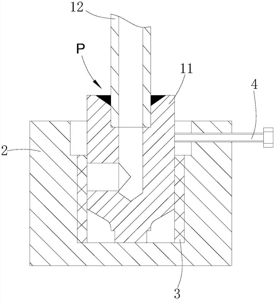
[0023] like Figures 3 to 4 shown

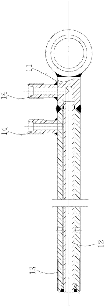
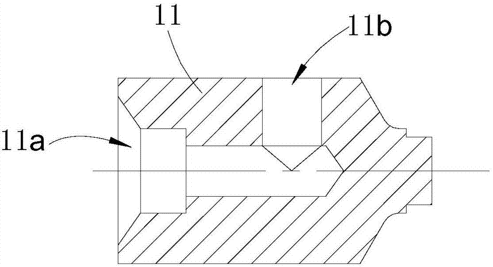
[0024] The positioning tooling includes a fixed seat 2, a limit bolt 4 and a sealing ring 3.

[0025] The fixed seat 2 is generally cylindrical, and the upper end surface of the fixed seat 2 is provided with a positioning groove that cooperates with the piston rod head 11. The positioning groove is a two-stage stepped groove, and the positioning groove is the first stage groove 21 and the second stage groove from top to bottom. Two-stage groove 22, the diameter of the first-stage groove 21 is greater than the diameter of the second-stage groove 22;

[0026] The side wall of the fixed seat 2 is provided with a limiting threaded hole (not shown) communicated with the first-stage groove 21, and the sealing ring 3 is set in the second-stage groove 22, and the height of the sealing ring 3 set is the same as that of the second-stage groove. 22 in the same width.

[0027] When the rod head 11 of the internal oil circuit type piston rod is welded...


PUM


Abstract

The invention provides a welding positioning tool for inner oil path type piston rod. The welding positioning tool comprises a fixing seat and sealing rings; positioning grooves matched with a pistonrod head are formed in the upper end surface of the fixing seat; the sealing rings sleeve in the positioning grooves; the piston rod head is matched with the fixing seat; and the piston rod head extends into the positioning grooves and the sealing rings seal oil ports of the piston rod head. The welding positioning tool has the beneficial effects that the problem of auxiliary positioning between the piston rod head and a core tube is solved; the welding operation of the inner oil path type piston rod is simplified, and the working efficiency is improved. The invention further provides a pressure testing method of the inner oil path type piston rod. The method comprises the following steps of matching the welded piston rod head and the core tube with the positioning tool; then placing the welded piston rod head, the core tube and the welding positioning tool of the inner oil path type piston rod into the water; enabling the end part of the core tube is communicated with a gas source; and observing whether the welding position between the piston rod head and the core tube is sealed or not. The pressure testing method has the beneficial effects that the pressure test process is simpleand clear, the pressure test efficiency is greatly improved, and the labor intensity is reduced.

Description

technical field [0001] The invention relates to a positioning tool, in particular to a positioning tool used in the welding operation of the rod head and the core pipe of an internal oil circuit piston rod. [0002] The invention also relates to a pressure test method after the welding of the rod head and the core pipe of the internal oil passage piston rod is completed. Background technique [0003] The internal oil circuit piston rod has a special design and complex structure, such as Figures 1 to 2 As shown, the internal oil circuit type piston rod is usually divided into: rod head 11, core tube 12, outer casing 13 and oil port joint 14, the end surface of the rod head 11 is provided with an oil hole 11a, and the side wall of the rod head 11 is provided with a The oil port 11b connected to the oil hole 11a, the core tube 12 is fixed to the rod head 11, the inner hole of the core tube 12 communicates with the oil hole 11a of the rod head 11, and the rod head 11 and the co...

Claims


Application Information

Patent Timeline
Patent Type & Authority Applications(China)
IPC IPC(8): B23K37/04G01M3/08
CPCG01M3/088B23K37/0435
Inventor 孙鸿钧张景徐龙易新新叶李军鄢超王鹏飞穆浩
Owner BENGBU YELI MACHINERY
Why Eureka
Try Eureka