
Novel new energy automobile device

A new energy vehicle, a new type of technology, applied in the direction of vehicle parts, transportation and packaging, removable outer sheath, etc., can solve the problems of limited cooling effect, sales decline, impact, etc., to achieve easy installation and disassembly, convenient handling, The effect of simple device structure

Inactive Publication Date: 2018-05-04
惠安县南兴电子科技有限公司
View PDF9 Cites 0 Cited by
  • Summary
  • Abstract
  • Description
  • Claims
  • Application Information

AI Technical Summary

Problems solved by technology

During the sale of new energy vehicles, due to the limited parking area, some new energy vehicles in stock will be parked outside. However, with the arrival of summer, the direct sunlight makes the internal temperature of new energy vehicles continue to rise, which seriously affects the test drive. The mood of customers has led to a decline in sales performance. There are many existing awnings installed at the parking spots of new energy vehicles, but the cooling effect is limited and cannot meet the purpose of rapid cooling. There are major disadvantages and need to be improved.

Method used


Image

  • Novel new energy automobile device
  • Novel new energy automobile device
  • Novel new energy automobile device

Examples


Embodiment Construction

[0030] All the features disclosed in this specification, or all disclosed methods or steps in the process, except for mutually exclusive features and / or steps, can be combined in any manner.

[0031] Any feature disclosed in this specification (including any appended claims, abstract and drawings), unless specifically stated, can be replaced by other equivalent or equivalent alternative features. That is, unless otherwise stated, each feature is just one example of a series of equivalent or similar features.

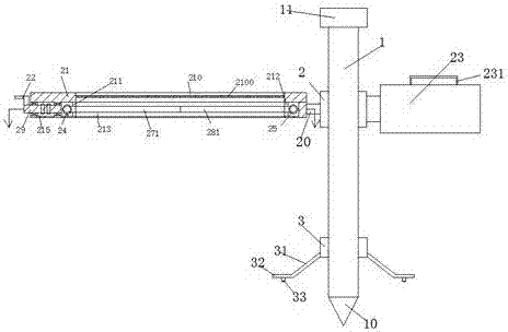
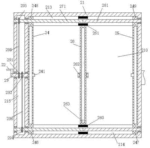
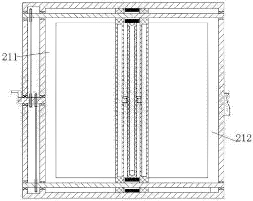
[0032] Such as Figure 1-7 As shown, a new energy vehicle device of the present invention includes a support rod 1, an upper fixing ring 2 and a lower fixing ring 3 smoothly mounted on the support rod 1, the upper fixing ring 2 and the lower fixing ring 3 Tightening members 34 are installed in both the upper fixing ring 2 and the connecting block 20 is fixed at the left end of the upper fixing ring 2, and the connecting block 20 is provided with a positioning device. The lef...


PUM


Abstract

A novel new energy automobile device comprises a supporting rod, an upper fixing ring and a lower fixing ring. The upper fixing ring and the lower fixing ring are installed on the supporting rod smoothly. Screwing pieces are installed in the upper fixing ring and the lower fixing ring correspondingly; a connecting block is fixedly arranged at the left end of the upper fixing ring and internally provided with an aligning device; an installing frame is rotatably installed at the left end of the upper fixing ring through the aligning device, and a matching block is fixedly installed at the rightend of the upper fixing ring; a protecting carrying device is arranged at the outer end of the lower fixing ring; a communicating groove communicating up and down is formed in the installing frame, and a shielding net is fixedly installed in the communicating groove; a left extending and retracting groove and a right extending and retracting groove which extend forwards and backwards are formed inthe positions, located at the lower end of the shielding net, of the left end wall and the right end wall of the communicating groove in a mode of corresponding in the left-right direction, wherein the open ends of the left extending and retracting groove and the right extending and retracting face the communicating groove; a front sliding groove and a rear sliding groove which extend leftwards and rightwards are formed in the positions, located at the lower end of the shielding net, of the front end wall and the rear end wall of the communicating groove in a mode of corresponding in the front-rear direction, wherein the open ends of the front sliding groove and the rear sliding groove face the communicating groove; the front sliding groove and the rear sliding groove communicate with theleft extending and retracting groove and the right extending and retracting groove; a left-front sliding block and a right-front sliding block are smoothly installed at the left end and the right endof the front sliding groove correspondingly; and a left-rear sliding block and a right-rear sliding block are smoothly installed at the left end and the right end of the rear sliding groove correspondingly.

Description

Technical field [0001] The invention relates to the technical field of new energy vehicles, in particular to a new type of new energy vehicle device. Background technique [0002] New energy vehicles are a vigorously developed industry in my country, and their future development prospects are broad. During the sale of new energy vehicles, due to the limited parking area, some new energy vehicles in stock will be parked outside. However, with the arrival of summer, the direct sunlight makes the internal temperature of new energy vehicles continue to rise, which seriously affects the test drive. The mood of customers has led to a decline in sales. There are many existing awnings in new energy vehicle parking spots, but their cooling effect is limited and cannot meet the purpose of rapid cooling. There are major drawbacks and need to be improved. Summary of the invention [0003] The purpose of the present invention is to provide a new type of new energy vehicle device, which can ov...

Claims


Application Information

Patent Timeline
IPC IPC(8): B60J11/04
CPCB60J11/04
Inventor 张金发
Owner 惠安县南兴电子科技有限公司
Learn More