Conductive busbar

A technology of busbars and convex ribs, which is applied in the field of rail transit, can solve the problems of difficult installation, slight movement of high and low points of busbars, and error-prone problems, so as to achieve simple and convenient installation of intermediate joints, elimination of slight movement of high and low points, and shorten construction period Effect

Pending Publication Date: 2018-05-04
NANJING JINCHENG RAIL TRANSPORT EQUIP
View PDF6 Cites 0 Cited by
  • Summary
  • Abstract
  • Description
  • Claims
  • Application Information

AI Technical Summary

Problems solved by technology

The currently used bus bar has a simple structure and a smooth inner wall. When the bus bar is connected to the bus bar, it is fixed only by bolts and gaskets through the middle joint of the bus bar. Not only is it difficult to install, it is prone to errors, and the overall connection is not tight enough. The high and low points of the busbar will move slightly due to vibration. When the pantograph is in contact with it, an arc will be generated. Long-term use will cause the problem of contact between the busbar and the pantograph, causing safety hazards

Method used


Image

  • Conductive busbar
  • Conductive busbar
  • Conductive busbar

Examples


Embodiment Construction

[0018] The present invention will be further described below in conjunction with the accompanying drawings.

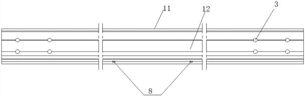
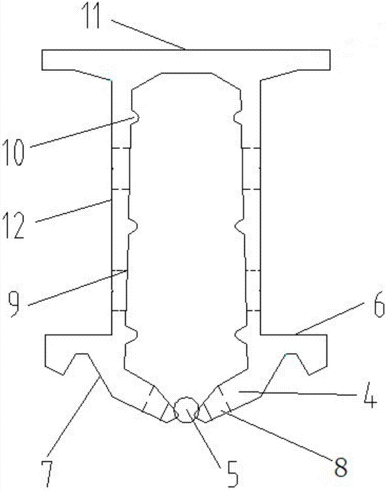
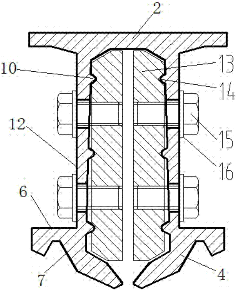
[0019] like figure 1 , figure 2 As shown, a conductive bus bar includes a top 11, a pair of side walls 12 are symmetrically extended below the top 11, and clamps 4 are arranged under each side wall 12, and the ends of the clamps 4 are formed between the ends for clamping. The elastic jaws of the contact wire 5 are provided with three ribs 10 from top to bottom on the opposite surfaces of the two side walls 12 , and the two ends of each side wall 12 are provided with connection ports 3 . Each chuck 4 extends horizontally with a trolley running platform 6, which is convenient for the operation of a special-purpose embedding trolley. V-shaped grooves 7 are arranged below each trolley running platform 6, which is convenient for embedding and thread removal of the embedding trolleys. Each V-shaped groove surface is provided with two pairs of symmetrical drain outlets 8 ...


PUM


Abstract

The invention discloses a conductive busbar, comprising a top portion. A pair of sidewalls are extended symmetrically from the bottom of the top portion, a clamp is arranged at the bottom of each sidewall, and an elastic jaw for clamping a contact wire is formed between the ends of the clamps; both opposing surfaces of the two sidewalls are provided with a plurality of ribs; each end of each sidewall is provided with a connection. The inner side of each sidewall of the conductive busbar is provided with self-locking positioning ribs to arrive at automatic positioning; when workers make connections, a middle connector is simpler and more convenient to mount, errors are avoided, and construction period is greatly shortened; the busbars can be automatically locked more firmly, and high- and low point micro-displacement due to vibrations is eliminated; the conductive busbar never strikes a pantograph under long-term working load, smooth passing of the pantograph is ensured, and safety andreliability are better.

Description

technical field [0001] The invention relates to the technical field of rail transit, in particular to a conductive bus bar. Background technique [0002] Electrified railways and urban rail transit generally use rigid catenary, that is, busbars made of aluminum alloy materials, to achieve mechanical and electrical connections. With the rapid development of urban rail transit, the quality and performance requirements of the busbar in the contact power supply system are getting higher and higher. The currently used bus bar has a simple structure and a smooth inner wall. When the bus bar is connected to the bus bar, it is fixed only by bolts and gaskets through the middle joint of the bus bar. Not only is it difficult to install, it is prone to errors, and the overall connection is not tight enough. The high and low points of the busbar will move slightly due to vibration. When the pantograph is in contact with it, an arc will be generated. Long-term use will cause the problem...

Claims


Application Information

Patent Timeline
Patent Type & Authority Applications(China)
IPC IPC(8): B60M1/12B60M1/24
CPCB60M1/12B60M1/24
Inventor 王一凡王若鸿殷纪元张娴毛家乐
Owner NANJING JINCHENG RAIL TRANSPORT EQUIP
Why Eureka
Try Eureka