Robot to remove debris from underwater hulls
A technology for underwater hulls and attachments. It is applied in the direction of hulls, ship construction, and ship cleaning devices. It can solve the problems of inaccurate operation in blind areas of vision, insufficient power of machines, and low underwater visibility, so as to enhance mobile flexibility and stability. Safety, reduce manufacturing cost, cleaning effect and safety effect
- Summary
- Abstract
- Description
- Claims
- Application Information
AI Technical Summary
Problems solved by technology
Method used
Image
Examples
Embodiment 1
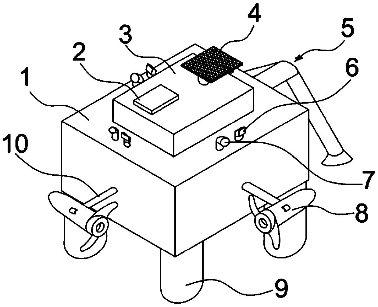
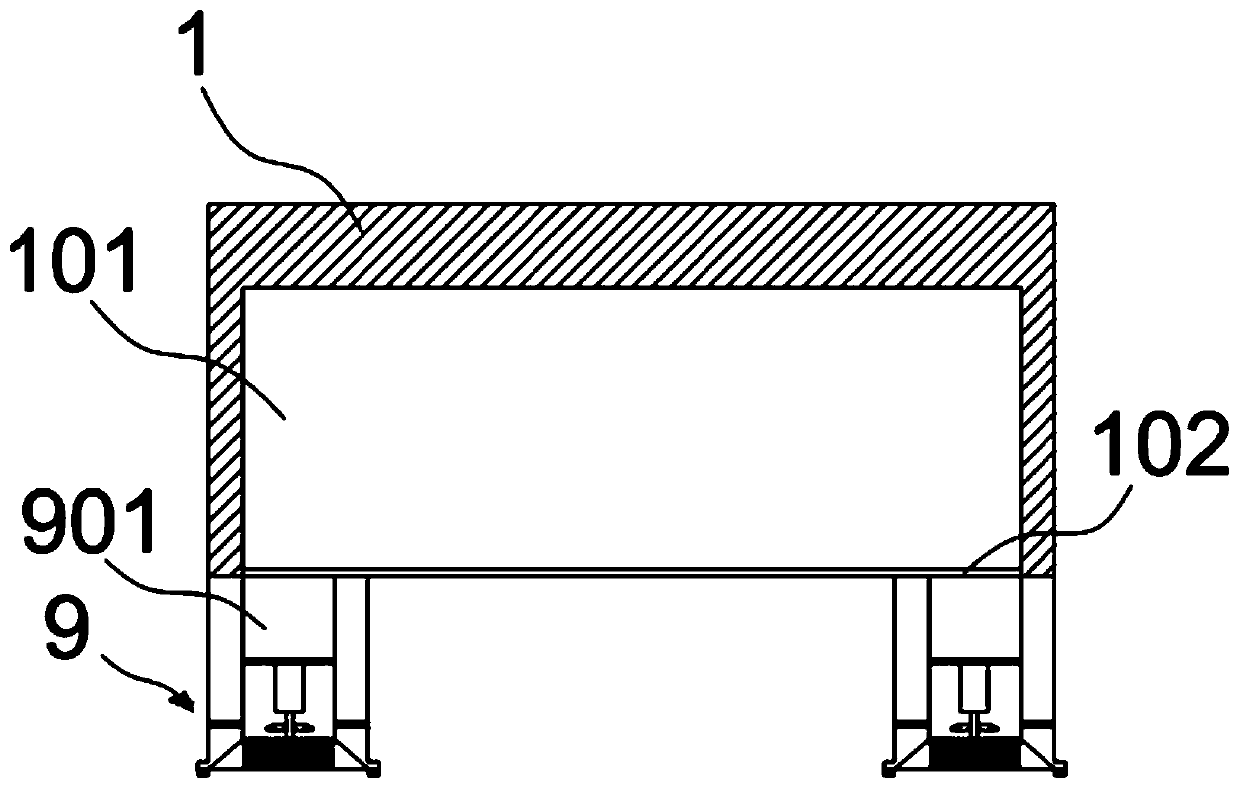
[0026] Such as figure 1 , 6, 7, the robot for removing underwater hull attachments includes a frame 1, the frame 1 is a cuboid, the side is provided with a propeller 8, the propeller 8 is provided with a paddle 801, the paddle 801 is hollow inside, and the middle part is provided with There is a partition 801a, and evenly distributed support bars 801b are connected between the upper and lower surfaces of the partition 801a and the hollow inner wall of the paddle 801, four cleaners 9 are evenly distributed on the bottom surface, a battery 3 is arranged in the middle of the surface, and a control panel is connected to the surface of the battery 3 2. The surface of the storage battery 3 is also connected with a solar receiving panel 4 through a telescopic rod. Cameras 6 and detection lights 7 are arranged around the surface of the frame 1. One side of the frame 1 is also connected with an adsorption device 5. The control panel 2 is provided with a water surface. The remote contr...
Embodiment 2
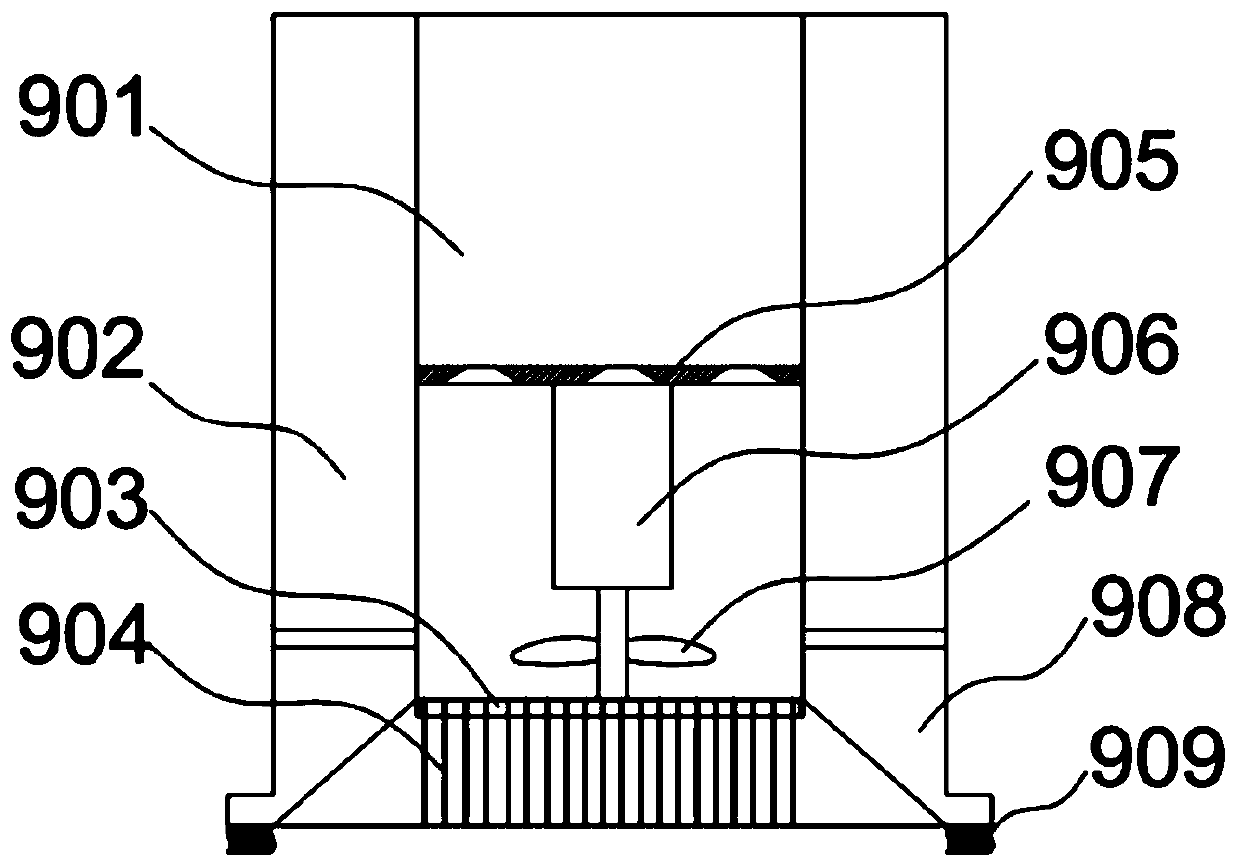
[0032] Such as figure 2 , 3 As shown, this embodiment is further optimized on the basis of Embodiment 1: the sweeper 9 is cylindrical, and an inner cylinder is arranged inside, the upper part of the inner cylinder is a collection chamber 901, and the middle part of the inner cylinder is provided with a collection plate 905, The surface of the collecting plate 905 is provided with a trapezoidal hole, the bottom of the collecting plate 905 is connected with a gear pump 906, the rotating shaft of the gear pump 906 is provided with suction blades 907, and the top of the rotating shaft is connected with a disc-shaped mesh plate 903, and the bottom surface of the mesh plate 903 is evenly distributed. There is a steel brush 904, the inner cylinder and the inner wall of the cleaner 9 housing form a paint chamber 902, the lower part of the paint chamber 902 is provided with an opening and closing plate, and the bottom and outer arms of the cleaner 9 are provided with a brush 909, when...
Embodiment 3
[0035] Such as Figure 4 , 5 As shown, this embodiment is further optimized on the basis of Embodiment 1: the side of the frame 1 is connected to the side of the frame 1 through the connecting shaft 509, and the bottom of the connecting shaft 509 is connected with two support rods 502 that can rotate around the connecting shaft 509 , a PLC controller 503 is provided on the support rod 502, a water pump 505 is connected to the other support rod 502, a three-way valve 508 is connected to the bottom of the support rod 502, one of the three-way valves 508 is connected to a suction cup 501, and one is connected to a water pipe 504, the other end of the water pipe 504 is connected to the three-way valve 508 on the other support bar 502, one is connected to the nozzle 507, and the junction with the nozzle is provided with a solenoid valve 506, and the PLC controller 503 is respectively connected to the three-way valve 508 on the two support bars 502. The electromagnetic valve 506 is...
PUM
 Abstract
Description
Claims
Application Information
 - R&D
- Intellectual Property
- Life Sciences
- Materials
- Tech Scout
- Unparalleled Data Quality
- Higher Quality Content
- 60% Fewer Hallucinations
Browse by: Latest US Patents, China's latest patents, Technical Efficacy Thesaurus, Application Domain, Technology Topic, Popular Technical Reports.
© 2025 PatSnap. All rights reserved.Legal|Privacy policy|Modern Slavery Act Transparency Statement|Sitemap|About US| Contact US: help@patsnap.com


