Hoisting mechanism automatic rope-arranging device

A hoisting mechanism and automatic rowing technology, applied in the direction of hoisting device, mainspring mechanism, etc., can solve the problems of shortening the service life of the wire rope, wrapping at one end of the drum, and the wire rope running out, preventing kinks and achieving reasonable structural design. , the effect of small radial force

Active Publication Date: 2018-05-04
德马科起重机械有限公司
View PDF10 Cites 11 Cited by
  • Summary
  • Abstract
  • Description
  • Claims
  • Application Information

AI Technical Summary

Problems solved by technology

[0002] Due to the long length of the steel wire rope on the crane drum, the steel wire rope needs to be coiled in multiple layers on the drum. Due to the mutual friction and extrusion force of the steel wire ropes, it is easy to appear disordered ropes, rope bites, and rope squeezes, resulting in wire rope damage. The service life is shortened, which affects the working efficiency of the lifting equipment. In addition, when the crane lifts heavy objects, there will be a phenomenon of oblique pull, which will easily cause the wire rope to wrap around one end of the drum, and even the wire rope will run out of the drum and cause safety accidents. In order to prevent Accidents occur when the wire rope is messed up on the surface of the drum. It is usually necessary to install a rope guide device on the drum to arrange the wire rope

Method used


Image

  • Hoisting mechanism automatic rope-arranging device

Examples


Embodiment 1

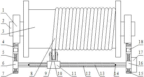
[0014] Such as figure 1 As shown, an automatic rope-rowing device for a hoisting mechanism includes two hinge seats 1, a main shaft 2 is arranged between the two hinge seats 1, a drum 3 is arranged on the main shaft 2, and the A wire rope 8 is wound on the drum 3, and the end of the wire rope 8 on the drum 3 is set in the rope groove 10 on the outer circumferential surface of the guide wheel 9, and the guide wheel 9 is rotated and arranged on the guide seat 11 Above, the guide seat 11 is connected to the threaded rod A12 through a threaded connection, the threaded rod A12 is arranged parallel to the main shaft 2, and the upper part of the threaded rod A12 is provided with a limit rod 13 parallel to it. Sliding connection between the rod 13 and the guide seat 11, the two ends of the limit rod 13 and the threaded rod A12 are respectively connected on the slider A6 and the slider B16, and the threaded rod A12 is connected with the slider A6 and the slider Rotation connection bet...

Embodiment 2

[0017] Such as figure 1 As shown, an automatic rope-rowing device for a hoisting mechanism includes two hinge seats 1, a main shaft 2 is arranged between the two hinge seats 1, a drum 3 is arranged on the main shaft 2, and the A wire rope 8 is wound on the drum 3, and the end of the wire rope 8 on the drum 3 is set in the rope groove 10 on the outer circumferential surface of the guide wheel 9, and the guide wheel 9 is rotated and arranged on the guide seat 11 Above, the guide seat 11 is connected to the threaded rod A12 through a threaded connection, the threaded rod A12 is arranged parallel to the main shaft 2, and the upper part of the threaded rod A12 is provided with a limit rod 13 parallel to it. Sliding connection between the rod 13 and the guide seat 11, the two ends of the limit rod 13 and the threaded rod A12 are respectively connected on the slider A6 and the slider B16, and the threaded rod A12 is connected with the slider A6 and the slider Rotation connection bet...


PUM


Abstract

The invention relates to a hoisting mechanism automatic rope-arranging device. The hoisting mechanism automatic rope-arranging device comprises two supporting hinge seats. A spindle is arranged between the two supporting hinge seats, a rolling drum is arranged at the spindle, the rolling drum is wound with a steel wire rope, the tail end of the steel wire rope at the rolling drum is arranged in arope groove in the outer circumferential surface of a rope guiding wheel, and the rope guiding wheel is rotatably arranged on a guiding seat; the guiding seat is in threaded connection with a threadedrod A, a limiting rod is parallelly arranged above the threaded rod A, the two ends of each of the limiting rod and the threaded rod A are connected to a sliding block A and a sliding block B correspondingly, and the sliding block A and the sliding block B are slidably arranged in horizontal sliding grooves in a supporting frame A and a supporting frame B correspondingly; and the sliding block Aand the sliding block B are in threaded connection with a threaded rod B, a motor A and a motor B are connected with the outer ends of the threaded rod A and the threaded rod B correspondingly, and travel switches are arranged at the two ends of the lifting rod correspondingly. In general, the hoisting mechanism automatic rope-arranging device has the advantages that the structural design is reasonable, the steel wire rope can be effectively prevented from twisting together, and radial force borne by a guiding device is small.

Description

technical field [0001] The invention belongs to the technical field of hoisting, and in particular relates to a rope arranging device, in particular to an automatic rope arranging device for a hoisting mechanism. Background technique [0002] Due to the long length of the steel wire rope on the crane drum, the steel wire rope needs to be coiled in multiple layers on the drum. Due to the mutual friction and extrusion force of the steel wire ropes, it is easy to appear disordered ropes, rope bites, and rope squeezes, resulting in wire rope damage. The service life is shortened, which affects the working efficiency of the lifting equipment. In addition, when the crane lifts heavy objects, there will be a phenomenon of oblique pull, which will easily cause the wire rope to wrap around one end of the drum, and even the wire rope will run out of the drum and cause safety accidents. In order to prevent Accidents occur when the wire rope is messed up on the surface of the drum. It i...

Claims


Application Information

Patent Timeline
IPC IPC(8): B66D1/38B66D1/12
Inventor 董彦波丁一董爱军
Owner 德马科起重机械有限公司
Why Eureka
Try Eureka