Take-up device for wet thread drying machine

A wire take-up device and dryer technology, which is applied in drying, drying solid materials, and dry cargo handling, etc., can solve the problems of incomplete drying and wet wires, and achieve simple structure, convenient operation, and high drying efficiency high effect

Pending Publication Date: 2018-05-04
GUIZHOU UNIV +1
View PDF7 Cites 0 Cited by
  • Summary
  • Abstract
  • Description
  • Claims
  • Application Information

AI Technical Summary

Problems solved by technology

[0002] The existing wet thread drying method is to send the wet thread winding drum directly into the drying room and use hot air for drying. This drying method has the following disadvantages. Since the wet thread is fixedly wound on the barrel, The drying method is also drying from the outside to the inside, resulting in incomplete drying, that is, the external wet line is dry, but the internal wet line is still wet

Method used


Image

  • Take-up device for wet thread drying machine
  • Take-up device for wet thread drying machine
  • Take-up device for wet thread drying machine

Examples


Embodiment Construction

[0019] Below in conjunction with accompanying drawing and specific embodiment the invention is further introduced:

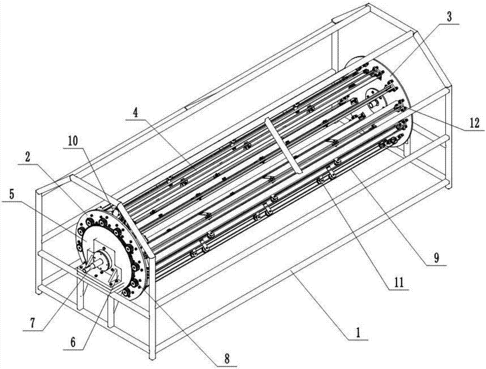
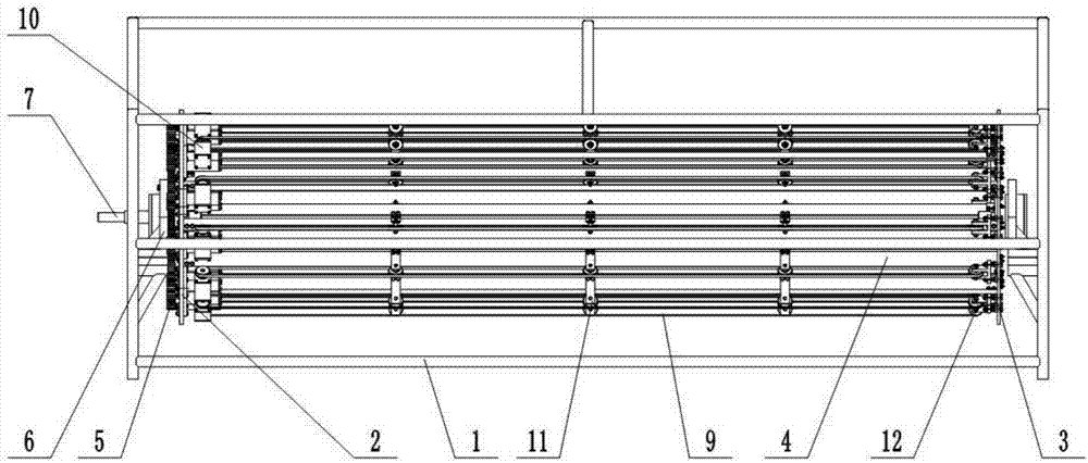
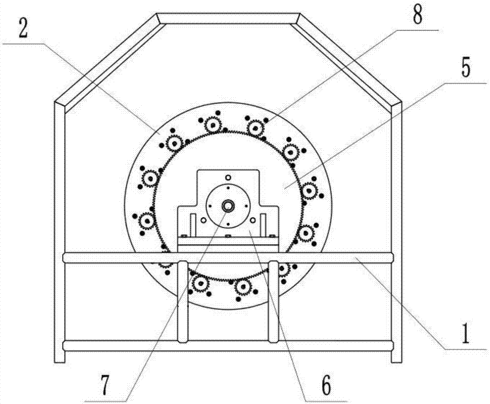
[0020] refer to Figure 1 to Figure 4 In this embodiment, a wire take-up device for a wet thread dryer includes a frame 1, a front end baffle 2 and a rear end baffle 3, and the front end baffle 2 and the rear end baffle 3 are respectively arranged in rotation through a bearing seat 6. On both sides of the frame 1, the front end baffle 2 is connected to the input shaft 7, and the input shaft 7 drives the front end baffle 2 to rotate, and the front end baffle 2 and the rear end baffle 3 are rigidly connected by cylindrical angle steel 4 arranged at intervals, A sun gear 5 parallel to the end surface of the front end baffle 2 is fixedly connected to the bearing seat 6 of the front end baffle 2, and a plurality of planetary gears 8 meshing with the sun gear 5 are arranged at intervals on the front end baffle 2, and the planetary gears 8 pass through The transmissio...


PUM


Abstract

The invention discloses a take-up device for a wet thread drying machine. The take-up device comprises a rack, a front-end baffle and a rear-end baffle. The front-end baffle and the rear-end baffle are arranged at the two sides of the rack in a rotating mode through bearing pedestals separately. The front-end baffle is connected with an input shaft. The front-end baffle and the rear-end baffle arein rigid connection through steel angles which are arranged at intervals. The bearing pedestal of the front-end baffle is fixedly connected with a sun gear which is parallel to the end face of the front-end baffle. Planetary gears engaged with the sun gear are arranged on the front-end baffle at intervals. The planetary gears are connected with a belt conveying mechanism between the front-end baffle and the rear-end baffle through driving elements. Compared with the prior art, wet threads can be wound and taken up, and meanwhile the wound wet threads can make axial movement and further be output from the output end of the take-up device so that the continuous needs for the wet threads at the downstream procedures can be met.

Description

technical field [0001] The invention relates to a thread take-up device of a wet thread dryer, belonging to the technical field of thread take-up and drying. Background technique [0002] The existing wet thread drying method is to send the wet thread winding drum directly into the drying room and use hot air for drying. This drying method has the following disadvantages. Since the wet thread is fixedly wound on the barrel, The drying method is also drying from the outside to the inside, resulting in incomplete drying, that is, the external wet line is dry, but the internal wet line is still wet. In addition, this method also meets the needs of the continuous process for the silk thread, which is not conducive to improving production efficiency. Contents of the invention [0003] The technical problem to be solved by the present invention is to provide a wire take-up device for a wet wire dryer to solve the technical problems raised in the background art above. [0004] ...

Claims


Application Information

Patent Timeline
Patent Type & Authority Applications(China)
IPC IPC(8): F26B25/00B65H75/42
CPCF26B25/003B65H75/42
Inventor 李家春张雷邹中妃陈跃威
Owner GUIZHOU UNIV
Why Eureka
Try Eureka