
Novel partial-pressure mass spectrometer calibration device and method

A technology of calibration device and partial pressure, applied in the direction of measurement device, instrument calibration, measurement of fluid pressure, etc., can solve the problems of large measurement uncertainty of calibration results and inability to prepare gas according to actual needs, so as to reduce measurement uncertainty. degree of effect

Active Publication Date: 2018-05-04
LANZHOU INST OF PHYSICS CHINESE ACADEMY OF SPACE TECH
View PDF4 Cites 4 Cited by
  • Summary
  • Abstract
  • Description
  • Claims
  • Application Information

AI Technical Summary

Problems solved by technology

[0003] The disadvantages of this system are: (1) only the prepared mixed gas with known components can be used for calibration, and the gas cannot be prepared according to actual needs; The gas state is a viscous flow state, and the gas state changes to a molecular flow state after sample injection, resulting in a change in the composition of the mixed gas after sample injection, requiring complex theoretical calculations to correct the calibration results; (3) The reference standards used are respectively It is an ionization vacuum gauge and a capacitance film vacuum gauge, which leads to a large measurement uncertainty in its calibration results

Method used


Image

  • Novel partial-pressure mass spectrometer calibration device and method

Examples


Embodiment 1

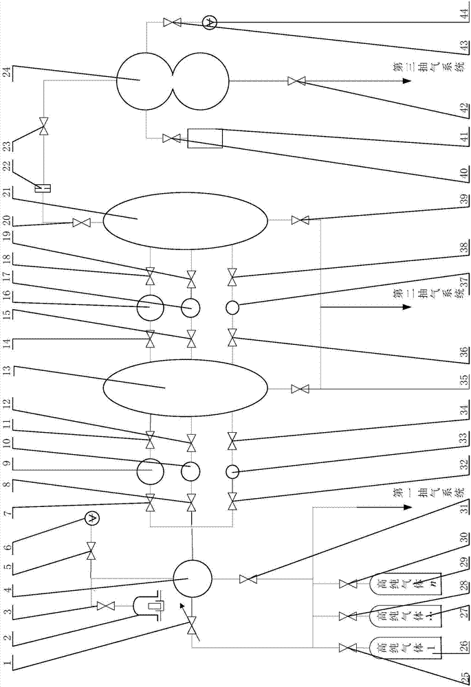
[0038] A new type of partial pressure mass spectrometer calibration device, mainly composed of fine-tuning valve 1, piston pressure gauge 2, sample preparation chamber 4, multiple high-purity gas cylinders, capacitance film vacuum gauge 6, primary sampling chamber 13, secondary sampling chamber Chamber 21, sampling chamber, small hole 22, calibration chamber 24, separation gauge 44 and air extraction system; wherein

[0039] The sample preparation chamber 4 is connected with the piston pressure gauge 2 and the capacitance film vacuum gauge 6 respectively, and the sample preparation chamber 4 is also connected with a plurality of high-purity gas cylinders connected in parallel through the fine-tuning valve 1; the sample preparation chamber 4 is connected with the A plurality of sampling chambers with different volumes are connected in parallel between the primary sampling chamber 13, and a plurality of sampling chambers with different volumes are connected in parallel between th...

Embodiment 2

[0049] In this embodiment, there are three sampling chambers connected in parallel between the sample preparation chamber 4 and the primary sampling chamber 13, and three sampling chambers connected in parallel between the primary sampling chamber 13 and the secondary sampling chamber 21, Specifically:

[0050] A new calibration device for partial pressure mass spectrometer, mainly composed of fine-tuning valve 1, piston pressure gauge 2, valve 3, 5, 7, 8, 11, 12, 14, 15, 18, 19, 20, 23, 25, 28, 30, 31, 32, 34, 35, 36, 38, 39, 40, 42, 43, sample preparation chamber 4, capacitance thin film vacuum gauge 6, first sampling chamber 9, second sampling chamber 10, primary sampling chamber 13. The fourth sampling chamber 16, the fifth sampling chamber 17, the second sampling chamber 21, the small hole 22, the calibration chamber 24, n high-purity gas cylinders 26, 27, 29, the third sampling chamber 33, the sixth sampling The chamber 37, the separation gauge 44, the first air extract...

Embodiment 3

[0062] In this embodiment, the gas to be configured is a mixed gas of He and Ar, and the volume ratio thereof is 1:4.

[0063] like figure 1 As shown, the novel partial pressure mass spectrometer calibration device designed by the present invention consists of a trim valve 1, a piston pressure gauge 2, valves 3, 5, 7, 8, 11, 12, 14, 15, 18, 19, 20, 23, 25 , 28, 30, 31, 32, 34, 35, 36, 38, 39, 40, 42, 43, sample preparation chamber 4, capacitance film vacuum gauge 6, first sampling chamber 9, second sampling chamber 10, primary Sampling chamber 13, fourth sampling chamber 16, fifth sampling chamber 17, secondary sampling chamber 21, small hole 22, calibration chamber 24, high-purity gas 26, 27, 29, third sampling chamber 33, sixth sampling The chamber 37, the calibrated pressure mass spectrometer 41, the separation gauge 44 and the like are composed.

[0064] In this embodiment, it is preferable to design or select each component as follows: the measurement accuracy of the pi...


PUM


Abstract

The invention provides a novel partial-pressure mass spectrometer calibration device, which mainly comprises a fine adjustment valve, a piston pressure meter, a sample preparation chamber, a pluralityof high-purity gas cylinders, a capacitive film vacuum meter, a first-stage sample feeding chamber, a second-stage sample feeding chamber, a sampling chamber, a small hole, a calibration chamber, a separation gauge and an air pumping system. The sample preparation chamber is respectively connected with the piston pressure meter and the capacitive film vacuum gauge. The sample preparation chamberis also connected with the plurality of high-purity gas cylinders which are connected in parallel through the fine adjustment valve. A plurality of sampling chambers with different volumes are connected between the sample preparation chamber and the first-stage sample feeding chamber in parallel. A plurality of sampling chambers with different volumes are connected between the first-stage sample feeding chamber and the second-stage sample feeding chamber in parallel. The second-stage sample feeding chamber is sequentially connected with the small hole and the calibration chamber in sequence. The calibration chamber is respectively connected with a to-be-calibrated differential pressure mass spectrometer and the separation gauge. The sample preparation chamber, the first-stage sample feeding chamber, the second-stage sample feeding chamber and the calibration chamber are connected with the air pumping system. According to the invention, actually required mixed gases can be configured according to customer requirements. In addition, it is ensured that gases do not change in the calibration process.

Description

technical field [0001] The invention relates to a novel partial pressure mass spectrometer calibration device and method, belonging to the technical field of vacuum measurement. Background technique [0002] Partial pressure mass spectrometers are widely used in various fields of industrial production, and the calibration of partial pressure mass spectrometers is an important research direction in the field of vacuum measurement. The document "Robert E.Ellefson.Methods for in situ QMScalibration for partial pressure andomposition analysis.Vacuum, 2014" introduces a partial pressure mass spectrometer calibration device, which combines two calibration methods: (1) direct the known group The mixed gas is introduced into the calibration chamber through a thin tube, and the partial pressure value of each component is obtained through a series of theoretical calculations with an ionization vacuum gauge as a reference standard; (2) First introduce a high-pressure mixed gas of about...

Claims


Application Information

Patent Timeline
IPC IPC(8): G01L27/00
CPCG01L27/002H01J49/0009H01J49/04
Inventor 李得天孙雯君成永军习振华袁征难赵澜董猛郭美如
Owner LANZHOU INST OF PHYSICS CHINESE ACADEMY OF SPACE TECH
Learn More