Rotation driving force receiving head, driving force transfer component and processing box

A technology of driving force and receiving head, which is applied in electrography, optics, instruments, etc., can solve problems such as unstable printing, inconvenient drop-off, failure of the driving head of the developing box, etc., and achieve the effect of stable and smooth rotation

Pending Publication Date: 2018-05-04
PRINT RITE UNICORN IMAGE PROD CO LTD
View PDF0 Cites 2 Cited by
  • Summary
  • Abstract
  • Description
  • Claims
  • Application Information

AI Technical Summary

Problems solved by technology

The distance between the protrusion of the universal drive head and its protective end face is about 10 mm, and the structure of the universal drive head is easy. higher production costs
[0004] There are new telescopic drive heads on the market, but with this simple telescopic drive head, when the developing cartridge is off the machine, the driving protrusions are likely to interfere with the drive head, which makes it inconvenient to unload, and it is easy to cause the developing cartridge to drive. header failure
Moreover, when printing in the machine, the drive head of the machine and the drive head on the toner box rotate together. Due to the imperfect structure, it is easy to cause problems in the cooperation between the drive head and the drive head of the toner box.
Moreover, the structure of this drive head is not very perfect, and it is unstable during the printing process, which leads to problems in the printing process and affects the actual printing and development effect.

Method used


Image

  • Rotation driving force receiving head, driving force transfer component and processing box
  • Rotation driving force receiving head, driving force transfer component and processing box
  • Rotation driving force receiving head, driving force transfer component and processing box

Examples


Embodiment Construction

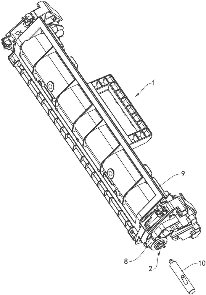
[0034] see figure 1 , figure 1It is a structural diagram of the processing box 1. The processing box 1 includes a powder bin 9, a roller (not marked) and a stirring frame (not marked) rotatably supported in the powder bin 9, and a driving force transmission assembly arranged at one end of the powder bin 9 2 and a limit mechanism 8 set on the driving gear of the driving force transmission assembly 2. In this embodiment, the roller is a developing roller, and the roller includes a roller body and a first driving force transmission device arranged on the axially outer end of the roller body. Components, the stirring frame is provided with a second driving force transmission part on the axial outer end, and the first driving force transmission part and the second driving force transmission part are respectively meshed with the driving force transmission assembly 2 through gears.

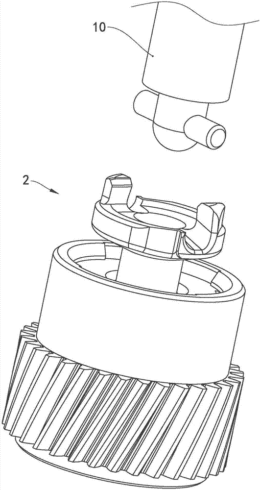
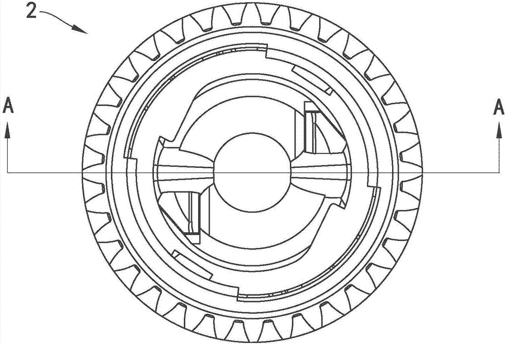
[0035] see Figure 2 to Figure 7 , showing the basic composition of the driving force transmission ...


PUM


Abstract

The invention provides a rotation driving force receiving head, a driving force transfer component and a processing box. The rotation driving force receiving head comprises an end part and a shaft part, wherein the end part is provided with a first surface connected with the shaft part and a second surface away from the shaft part; a concave spherical surface is arranged in the second surface; twoconvex claws extend out of the second surface; the two convex claws are in central symmetry relative to the axis of the rotation driving force receiving head; the surface of each convex claw is provided with an occlusal surface matching a driving component of an imaging device; a limiting slot is formed in each occlusal surface; the limiting slots are obliquely arranged along the radial directionof the end part; the upper ends of the limiting slots are located on the second surface and are connected with the spherical surface; the lower ends of the limiting slots are located on the peripheryof the first side surface. In the scheme, the connection between driving force connecting components is more stable and smoother, and the rotation work is stable without influencing the printing effect of the imaging device or causing poor printing.

Description

technical field [0001] The invention relates to the technical field of printing consumables, in particular to a rotary driving force receiving head, a driving force transmission assembly and a process box equipped with the driving force transmission assembly. Background technique [0002] An electrophotographic image forming apparatus such as a laser printer generally has a developing cartridge in it, and the developing cartridge can be detached from the printer. At present, the existing developing cartridges have the following categories: an integrated box composed of a photosensitive drum and a developing device, a charging device, and a cleaning device; The photosensitive drums of the above developing cartridges are all provided with a mechanism for receiving rotational driving force and driving the photosensitive drums. [0003] There is a developing cartridge, which provides a powder cartridge driving assembly, and the driving member is provided with a universal drivin...

Claims


Application Information

Patent Timeline
Patent Type & Authority Applications(China)
IPC IPC(8): G03G21/18G03G21/16
CPCG03G21/1857G03G21/1647
Inventor 杨晓锋丁文奕
Owner PRINT RITE UNICORN IMAGE PROD CO LTD
Why Eureka
Try Eureka