
Spiral bevel gear surface contact analysis method

A technology of spiral bevel gear and contact analysis, which is applied in the field of gear transmission and can solve problems such as inability of differential geometry, non-convergence in solving equations, difficulty in solving equations, etc.

Inactive Publication Date: 2018-05-04
CHANGAN UNIV
View PDF6 Cites 28 Cited by
  • Summary
  • Abstract
  • Description
  • Claims
  • Application Information

AI Technical Summary

Problems solved by technology

For spiral bevel gears with complex tooth surfaces, there are two main problems in this technology: (1) In order to obtain the contact point position, at least 5 nonlinear equations need to be solved, which puts higher requirements on the solution algorithm and initial value selection ; If the selection is not appropriate, the solution of the equations will not converge or the calculation results will be meaningless, further considering the influence of the installation error, the solution of the equations will be very difficult
(2) When calculating the size and direction of the major axis of the contact ellipse, it is necessary to use complex differential geometry formulas to determine the main curvature and main direction of the tooth surface, which can only be mastered by professional and technical personnel; if the three-parameter envelope tooth surface is considered, the differential Geometry appears impotent

Method used


Image

  • Spiral bevel gear surface contact analysis method
  • Spiral bevel gear surface contact analysis method
  • Spiral bevel gear surface contact analysis method

Examples


Embodiment Construction

[0037] The present invention will be further described in detail below in conjunction with the accompanying drawings, which are explanations rather than limitations of the present invention.

[0038] A method for analyzing the tooth surface contact of a spiral bevel gear, comprising the following steps:

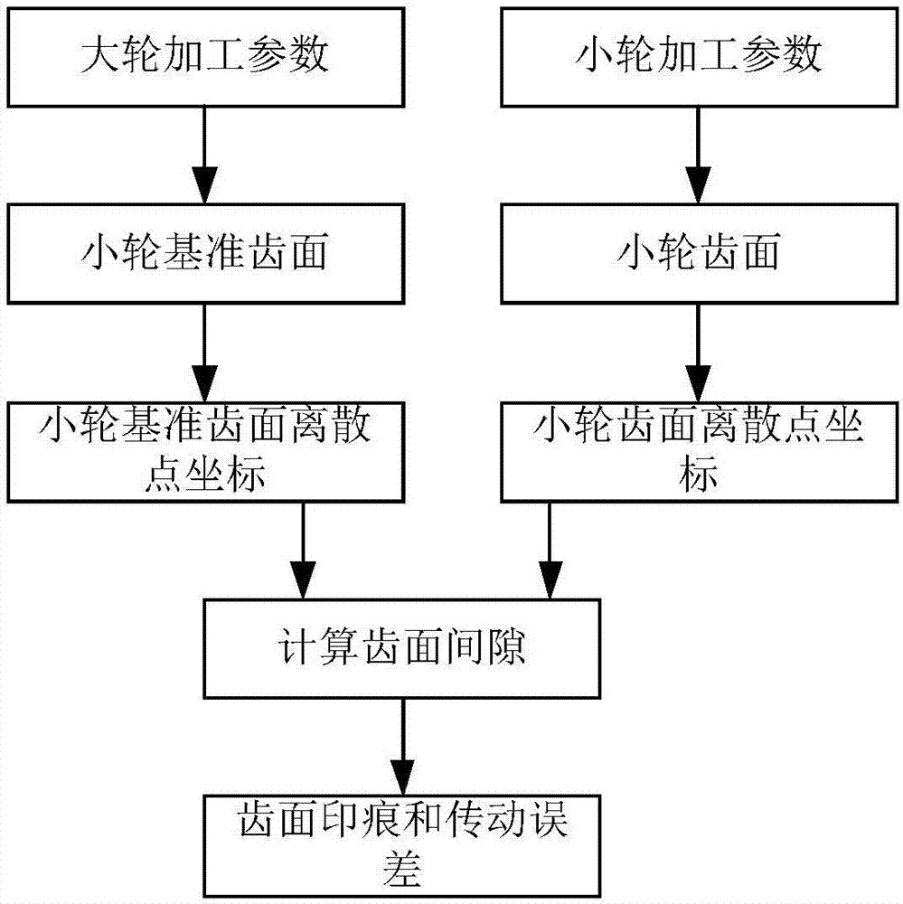
[0039] (1) Given the processing parameters of the large wheel, according to the coordinate transformation and meshing principle, deduce the tooth surface Σ of the large wheel 2 The position vector r 2 = r 2 (θ 2 ,φ 2 ) and the normal vector n 2 =n 2 (θ 2 ,φ 2 ), θ 2 , φ 2 is the surface coordinate parameter of the large wheel. According to the principle of gear shaping, the gear tooth surface Σ 2 is a hypothetical gear cutter, according to the roll ratio m 12 =z 1 / z 2 Process the small wheel reference tooth surface Σ 10 ,z 1 ,z 2 are the teeth numbers of the small wheel and the large wheel respectively, and their position vectors and the normal vector ...


PUM


Abstract

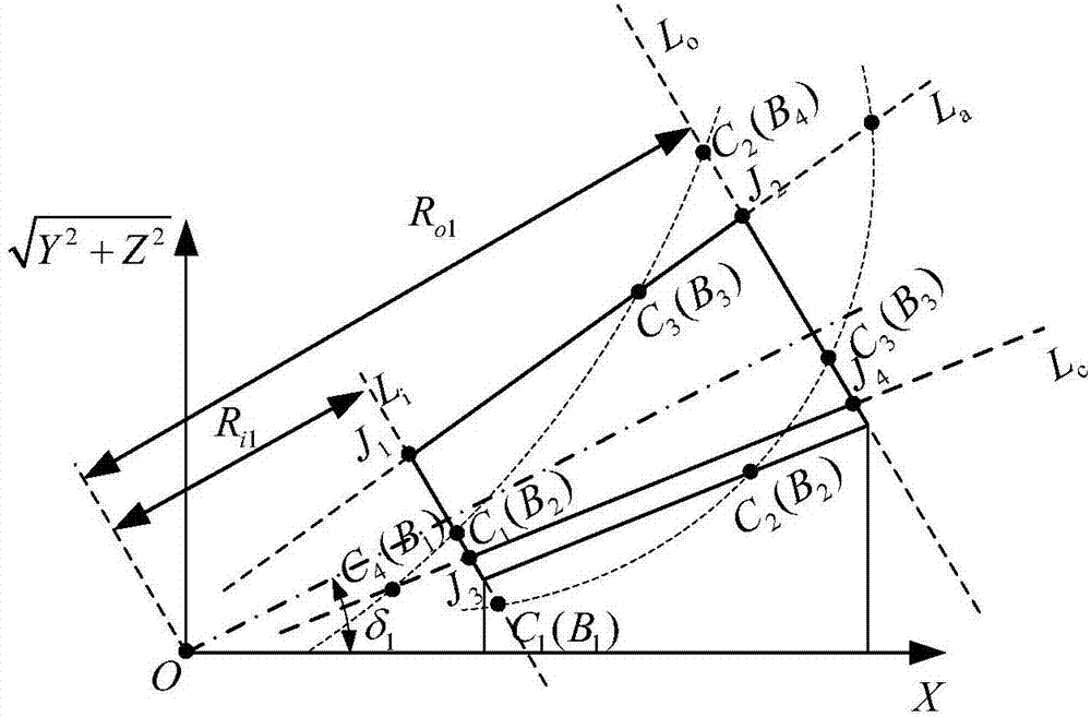
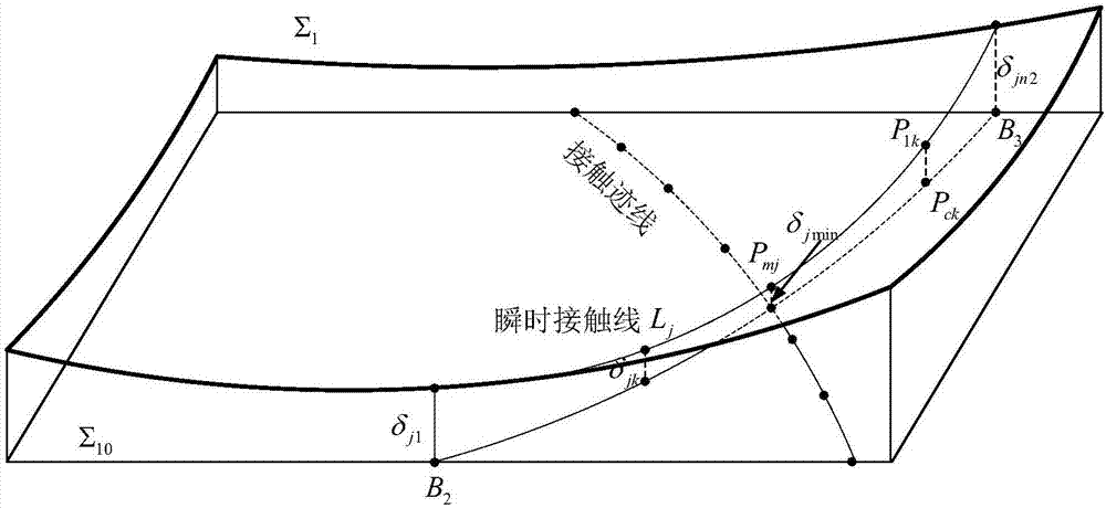
The invention discloses a spiral bevel gear surface contact analysis method. The method includes: taking a large gear as an imaginary generating gear tool to generate a small gear datum tooth surface;according to small wheel processing parameters and a linear cutting edge starting position, determining a boundary between an operating tooth surface and a transition curved surface, working out minimum and maximum processing corners of the large gear in an operating tooth surface range, and further calculating coordinates of the small gear datum tooth surface and a small gear tooth surface on aninstantaneous contact line correspondingly to obtain a gap between the two tooth surfaces; taking a minimum gap point on the instantaneous contact line as a contact point to obtain an approximate contact trace line, wherein the contact point is an effective contact point when the gap is smaller than 0.00635mm; converting all contact point minimum gaps into angular units to obtain an approximate transmission error. According to different geometrical conditions, two conditions namely edge contact and normal contact are included. Results of the approximate method are quite close to those of traditional theoretical methods, and engineering requirements can be met.

Description

technical field [0001] The invention belongs to the technical field of gear transmission, and in particular relates to a method for analyzing the tooth surface contact of a spiral bevel gear. Background technique [0002] Tooth surface contact analysis is to simulate the contact area and transmission error formed by the gear pair during the meshing process with the help of computer programs. It can comprehensively evaluate the meshing quality before gear processing. Significance. In general, tooth surface contact analysis is not applicable for fully conjugated line contact gear pairs, only for mismatched point contact gear pairs. The traditional tooth surface contact analysis is to obtain the contact point and its tooth surface contact parameters according to the continuous tangency condition of the two meshing tooth surfaces. The difficulty is to determine the contact point position and the contact ellipse parameters. For spiral bevel gears with complex tooth surfaces, th...

Claims


Application Information

Patent Timeline
Patent Type & Authority Applications(China)
IPC IPC(8): G06F17/50
CPCG06F30/17G06F30/20
Inventor 苏进展常乐浩刘永生贺朝霞
Owner CHANGAN UNIV
Learn More