Battery cell lead structure for battery module

A battery module and cell lead technology, which is applied to battery pack parts, secondary batteries, structural parts, etc., can solve the problem of inability to ensure the electrical continuity of the terminals of the electrical connection piece, and achieve the effect of ensuring reliability.

Inactive Publication Date: 2018-05-04
ANHUI OFFNENBACH NEW ENERGY TECH CO LTD
View PDF5 Cites 3 Cited by
  • Summary
  • Abstract
  • Description
  • Claims
  • Application Information

AI Technical Summary

Problems solved by technology

[0003] Existing battery modules mainly include battery cells and a supporting frame for supporting the battery cells. The connection between the cells and the outside world is through electrical connecting sheets. Since the cells are mostly standard parts, the electrical connecting sheets are mostly metal sheet structures. , when an electrical connection piece is connected to the terminal of a battery cell, it can also ensure electrical conduction. When multiple battery cells are arranged in parallel and spaced apart, when an electrical connection piece is connected to the terminal of multiple battery cells, sometimes it will be connected to the terminal There is a gap, and the electrical continuity between the electrical connection piece and the terminals of multiple cells cannot be ensured

Method used


Image

  • Battery cell lead structure for battery module
  • Battery cell lead structure for battery module
  • Battery cell lead structure for battery module

Examples


Embodiment Construction

[0023] combine Figure 1 to Figure 12 , the present invention is further described:

[0024] The battery lead wire structure for the battery module of the present invention is introduced below in conjunction with the entire battery module:

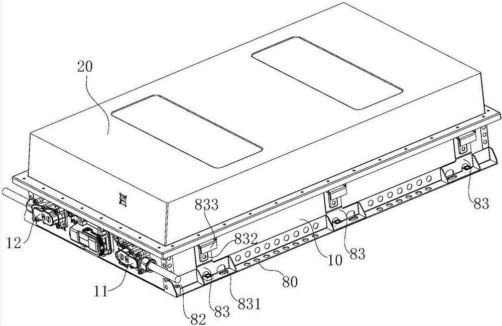
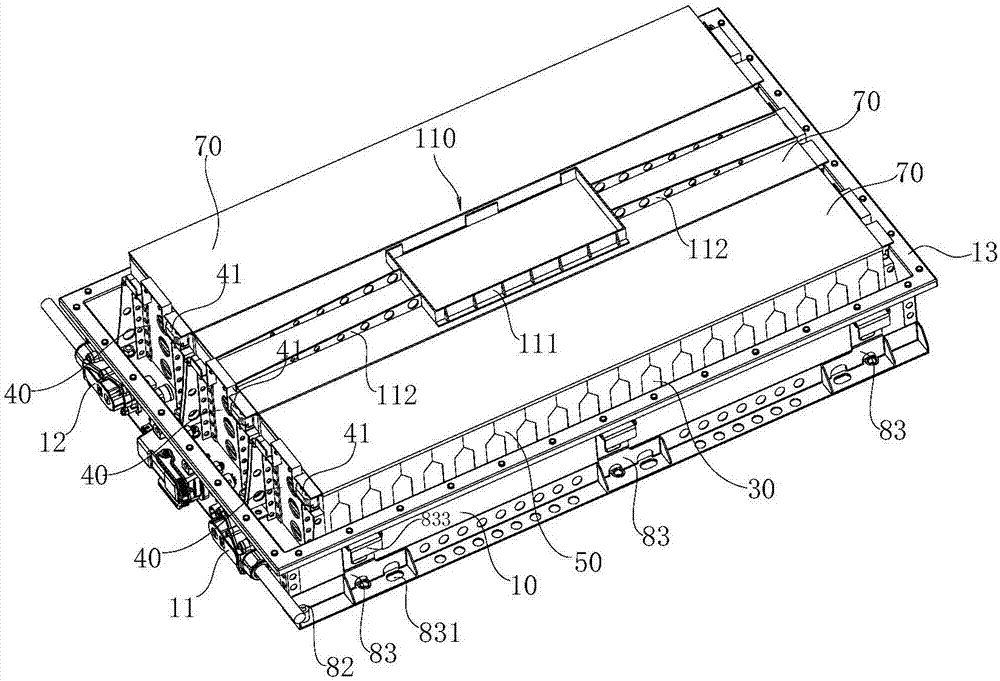
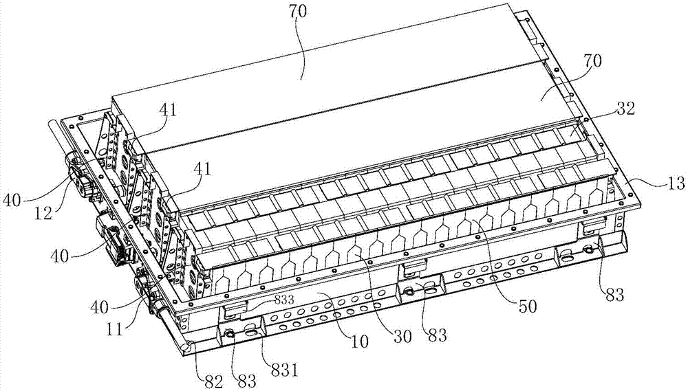
[0025] The battery module includes a bottom support 10 for installing the battery module. The bottom support 10 has an open box-like structure, and the side walls of the bottom support 10 are respectively provided with a module negative terminal 11 and a module positive connection terminal 12. The opening of the bottom bracket 10 is provided with a box cover 20. The battery module includes a plurality of battery packs arranged in parallel. The battery cell 30 located at the outermost side of the battery pack is provided with a supporting frame 40, and a locking screw 41 is arranged between the supporting frames 40 on both sides of the battery pack, and the locking screw 41 is parallel to the length direction of the battery pack and The e...


PUM


Abstract

The invention relates to a battery cell lead structure for a battery module. The battery cell lead structure comprises a bottom support for mounting the battery module, wherein the bottom support is of an open tank structure, and a module cathode connecting end and a module anode connecting end are respectively arranged on the side wall of the bottom support; the battery module comprises a plurality of battery packs which are arranged in parallel, and each battery pack comprises a plurality of battery cells which are sequentially arranged along the length direction of the bottom support, the battery cells on the outermost sides of battery packs are provided with support frames, locking screw rods are arranged between the support frames on two sides of the battery packs and are parallel tothe length directions of the battery packs, and two ends of the locking screw rods are fixed with the support frames on two sides of the battery packs; electric connecting pieces are arranged on wiring heads of the battery cells, extends towards two sides of the battery packs, are electrically connected with electric connecting heads on the support frames and are wave-shaped; and cover plates arearranged at the upper ends of the battery packs, and the lower plate surfaces of the cover plates prop against the electric connecting pieces. The wave-shaped electric connecting pieces prop against the cover plates, so that the conductance firmness between the electric connecting pieces and the battery cells can be guaranteed.

Description

technical field [0001] The invention relates to the technical field of power batteries for new energy vehicles, in particular to a battery cell lead wire structure for a battery module. Background technique [0002] Battery modules are the "heart" of electric vehicles. The battery module is the core part of providing power energy for new energy vehicles such as electric vehicles and hybrid vehicles. It can be understood that battery cells are combined in series and parallel, and a battery monitoring and management device (MCN) is installed to manage and control them. The structural design of the battery module can often determine the performance and safety of a battery box. Its structure must support, fix and protect the battery cells. At the same time, how to meet the requirements of overcurrent, current uniformity, how to meet the control of battery cell temperature, and whether to cut off the power when there is a serious abnormality, to avoid chain reactions, etc., wi...

Claims


Application Information

Patent Timeline
Patent Type & Authority Applications(China)
IPC IPC(8): H01M2/20H01M2/10H01M10/42H01M50/204H01M50/262H01M50/289H01M50/296H01M50/502
CPCH01M10/425H01M2010/4278H01M50/20H01M50/50Y02E60/10
Inventor 曹杰
Owner ANHUI OFFNENBACH NEW ENERGY TECH CO LTD
Why Eureka
Try Eureka