Wind power generating set and tower tube thereof

A tower tube and tube section technology, applied in the field of wind turbines and their towers, can solve the problems of high prefabrication cost, uncontrollable quality, inconvenient transportation, etc., achieve quality control, ensure connection reliability, and improve overall bearing capacity Effect

Inactive Publication Date: 2018-08-17
SANY ELECTRIC CO LTD
View PDF7 Cites 2 Cited by
  • Summary
  • Abstract
  • Description
  • Claims
  • Application Information

AI Technical Summary

Problems solved by technology

[0010] The purpose of the present invention is to provide a wind power generating set and its tower to solve the technical problems of inconvenient transportation, high prefabrication cost and uncontrollable quality in the prior art

Method used


Image

  • Wind power generating set and tower tube thereof
  • Wind power generating set and tower tube thereof
  • Wind power generating set and tower tube thereof

Examples


Embodiment 1

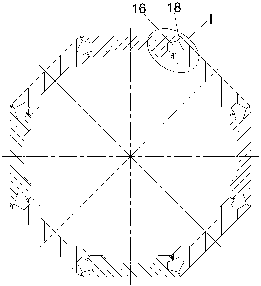
[0041] The tower tube of this embodiment includes at least one tube section in the height direction, such as figure 2 As shown, each tube section is composed of eight flat-shaped tower tube members 1 sequentially spliced ​​along the circumferential direction, and the cross-section is a regular octagon.

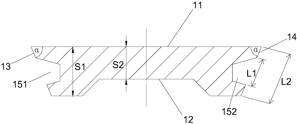
[0042] combine figure 1 As shown, the tower component 1 is specifically a flat plate structure surrounded by an outer facade 11 , an inner facade 12 , a first side elevation 13 and a second side elevation 14 .

[0043] Wherein, the exterior surface 11 is a plane as a whole.

[0044] In order to facilitate the splicing between the tower components 1, the angle α between the first side elevation 13 and the second side elevation 14 of the tower component 1 and the outer facade 11 is an acute angle, that is, from the outer facade 11 Gradually shrink towards the inner facade 12, and the specific value of the included angle α is set according to the actual structural design of the ...

Embodiment 2

[0058] Such as Figure 4-Figure 6 As shown, compared with Embodiment 1, the main difference of Embodiment 2 is that the wall thickness on both sides of the tower member 1 has not changed relative to the wall thickness of the middle section, and the wall thickness on both sides has not been thickened. The tower member 1 The inner facade 12 is a plane as a whole. This further simplifies the mold design of the tower component 1 and reduces the manufacturing cost of the tower component 1 . Apart from this, the other structures are basically the same, thus possessing all the above-mentioned advantages, which will not be repeated here.

Embodiment 3

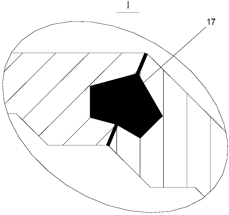
[0060] Such as Figure 7-Figure 9 As shown, compared with Embodiment 1, the main difference of Embodiment 3 is that the shape design of the first longitudinal slot groove 151 and the second longitudinal slot groove 152 are different, so that the shape of the volume cavity 16 formed by their mutual cooperation is different. In Example 3, the cross-sectional shape of the first longitudinal slot groove 151 and the second longitudinal slot groove 152 is semi-elliptical, and the shape of the volume chamber 16 formed is nearly elliptical. Apart from this, the other structures are basically the same, thus possessing all the above-mentioned advantages, which will not be repeated here.


PUM


Abstract

The invention relates to the technical field of wind power generation and particularly discloses a tower tube. The tower tube comprises at least one tube section in the height direction; each tube section is composed of at least three tower tube members which are spliced end to end in sequence in the circumferential direction; the adjacent tower tube members are mutually spliced and matched in theheight direction to form volume cavities; and the adjacent tower tube members are connected and fixed through grouting materials which fill in the volume cavities. Each tube section of the tower tubeis composed of and spliced by the tower tube members of the same structure, the mold design is greatly simplified, and the cost is reduced. The tower tube members are connected and fixed through thelongitudinal joint groove structure, and connection is safe and reliable. The invention further discloses a wind power generating set.

Description

technical field [0001] The invention relates to the technical field of wind power generation, in particular to a wind power generating set and a tower thereof. Background technique [0002] Wind power generators are equipment that convert wind energy into electrical energy. Wind energy is a new type of renewable energy with the most mature technology and the most large-scale development in the field of clean energy. With the increasing requirements for environmental protection, wind power technology has developed rapidly. . [0003] The tower is used to support the entire host and is the foundation of the wind turbine. As the key areas of wind power generation shift from the Three North regions to the central and southern regions with low wind speed, in order to make it possible to develop power generation in some low wind speed regions, the application of high towers / ultra-high towers (the super height of the hub exceeds 120 meters) has become unavoidable. Second choice. ...

Claims


Application Information

Patent Timeline
Patent Type & Authority Applications(China)
IPC IPC(8): F03D13/20
CPCF03D13/20Y02E10/72Y02E10/728Y02P70/50
Inventor 胡柱夏益民蒋琼
Owner SANY ELECTRIC CO LTD
Why Eureka
Try Eureka