Wind generating set, tower drum and component thereof
A tower and component technology, applied in the field of wind power generation, can solve the problems of inconvenient transportation, uncontrollable quality, and high prefabrication cost, and achieve the effects of improving overall bearing capacity, ensuring connection reliability, and high connection strength.
- Summary
- Abstract
- Description
- Claims
- Application Information
AI Technical Summary
Problems solved by technology
Method used
Image
Examples
Embodiment 1
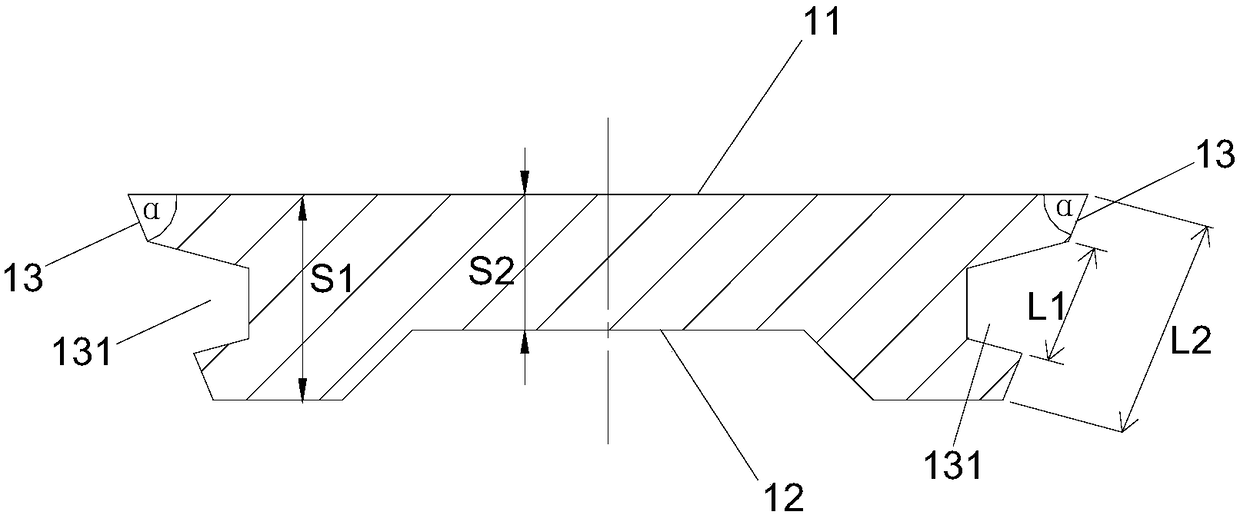
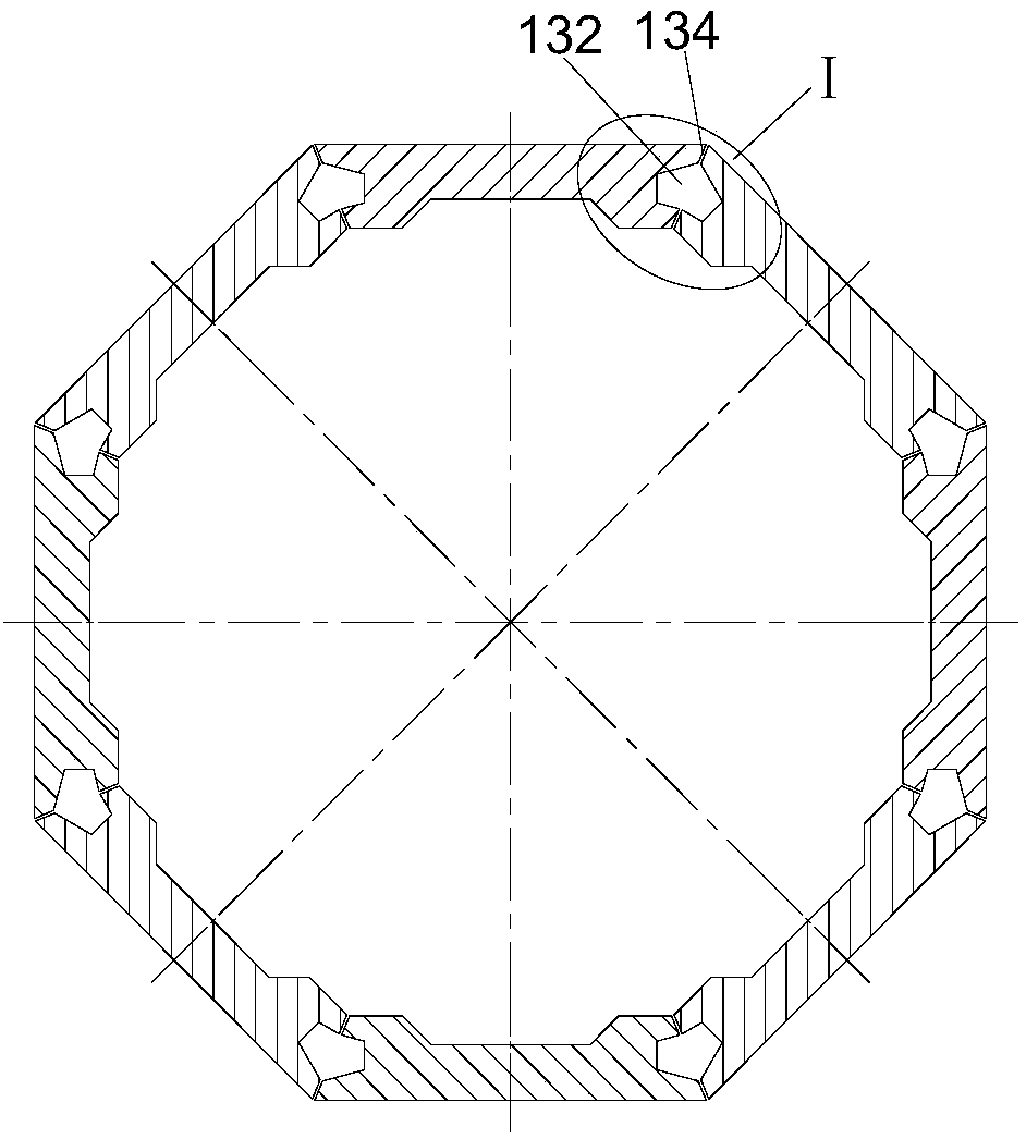
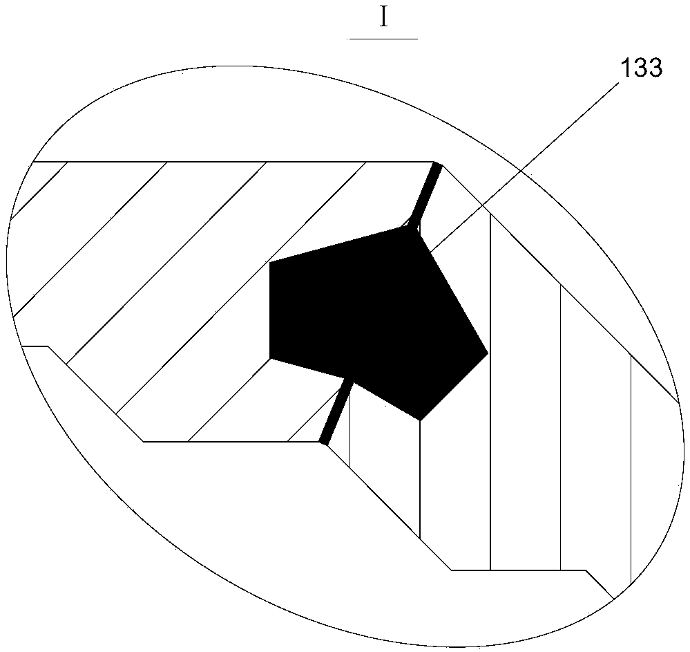
[0038] The tower tube of this embodiment includes at least one tube section in the height direction, such as figure 2 As shown, each tube section is composed of eight flat-shaped tower tube members 1 sequentially spliced along the circumferential direction, and the cross-section is a regular octagon.
[0039] combine figure 1 As shown, the tower component 1 is specifically a flat plate structure surrounded by an outer facade 11 , an inner facade 12 and two side facades 13 .
[0040] Wherein, the exterior surface 11 is a plane as a whole.
[0041] In order to facilitate splicing between the tower components 1, the angle α between the two side facades 13 of the tower component 1 and the outer facade 11 is an acute angle, that is, gradually shrinks from the outer facade 11 to the inner facade 12 , the specific value of the included angle α is set according to the actual structural design of the barrel section. In this embodiment, the barrel section is made by splicing eight ...
Embodiment 2
[0054] like Figure 4-Figure 6 As shown, compared with Embodiment 1, the main difference of Embodiment 2 is that the wall thickness on both sides of the tower member 1 has not changed relative to the wall thickness of the middle section, and the wall thickness on both sides has not been thickened. The tower member 1 The inner facade 12 is a plane as a whole. This further simplifies the mold design of the tower component 1 and reduces the manufacturing cost of the tower component 1 . Apart from this, the other structures are basically the same, thus possessing all the above-mentioned advantages, which will not be repeated here.
Embodiment 3
[0056] like Figure 7-Figure 9 As shown, compared with Embodiment 1, the main difference of Embodiment 3 is that the shape design of the longitudinal slot groove 131 is different, so the shape of the volume cavity formed by adjacent longitudinal slot grooves is different. In Embodiment 3, the longitudinal slot groove The cross-sectional shape of 131 is semi-elliptical, and the shape of the volume cavity formed is nearly elliptical. Apart from this, the other structures are basically the same, thus possessing all the above-mentioned advantages, which will not be repeated here.
[0057] It is worth noting that the above three embodiments are only partial examples, and are not intended to limit the present invention. Besides the above embodiments, there are other possibilities, such as the number of tower components that make up the tube section may not be limited to the embodiments One to eight in the third embodiment can also be more other possibilities, such as three, four, f...
PUM
 Abstract
Description
Claims
Application Information
 - R&D
- Intellectual Property
- Life Sciences
- Materials
- Tech Scout
- Unparalleled Data Quality
- Higher Quality Content
- 60% Fewer Hallucinations
Browse by: Latest US Patents, China's latest patents, Technical Efficacy Thesaurus, Application Domain, Technology Topic, Popular Technical Reports.
© 2025 PatSnap. All rights reserved.Legal|Privacy policy|Modern Slavery Act Transparency Statement|Sitemap|About US| Contact US: help@patsnap.com


