Electromagnetically actuated valve for hydraulic motor vehicle brake systems

Inactive Publication Date: 2000-11-28
ROBERT BOSCH GMBH
View PDF2 Cites 29 Cited by
  • Summary
  • Abstract
  • Description
  • Claims
  • Application Information

AI Technical Summary

Benefits of technology

The valve according to the invention has the advantage over the prior art that in a way similar to a proportional valve, it can be transferred, by controlling the magnetic force and with short strokes, to an arbitrary number of intermediate positions but without having to have the complicated design of a proportional valve. This mode of operation can be ascribed to the fact that the restoring spring essentially determines the course of the force engaging the tappet over the valve stroke, while the hydraulic force acting on the closing member has only subordinate influence, because of the diameter ratios of the inflow bore and the sealing diameter of the valve seat and because of the force deviation to the valve dome. A largely continuous flow control is therefore attainable with the valve of the invention. In many applications it can be used instead of proportional valves. In slip-controlled brake systems, the use of the valve of the invention makes it possible to achieve a higher closed-loop control quality and lower noise emissions than in the known valve.By means of the provisions recited in the dependent claims, advantageous refinements of and improvements to the valve defined by claim 1 are possible.With the embodiments defined herein a more-defined separation of the stream of pressure medium from the closing member or the valve seat is attained after the valve opens. Unstable flow forces are thus largely avoided.The refinement of the invention defined has the advantage that a stream of pressure medium once separated from the closing member and the valve seat, in its further course now no longer strikes the tappet. This precludes disruptive influences of flow forces.With the embodiment of the invention defined hereinafter, it is possible in a simple way to adjust the spring force of the restoring spring, for instance in the closing position of the seat valve, by adjusting the position of the sleeve relative to the tappet.One exemplary drawing of the invention is shown in simplified form and described in further detail in the ensuing description.FIG. 1 shows a longitudinal section through an electromagnetically actuated valve with a seat valve;FIG. 2 shows a detail II of FIG. 1 in the form of the seat valve, in the closing position, on a larger scale than in FIG. 1; andFIG. 3 shows a graph of the forces operative in the seat valve over the valve opening stroke.

Problems solved by technology

A magnetic circuit designed in this way requires corresponding space for installation and with other disadvantages prevents the disposition of such valves in a space-saving, tight package.
This lessens the mobility of such valves.
Moreover, their considerable switching noises are often disadvantageous.

Method used


Image

  • Electromagnetically actuated valve for hydraulic motor vehicle brake systems
  • Electromagnetically actuated valve for hydraulic motor vehicle brake systems
  • Electromagnetically actuated valve for hydraulic motor vehicle brake systems

Examples


Embodiment Construction

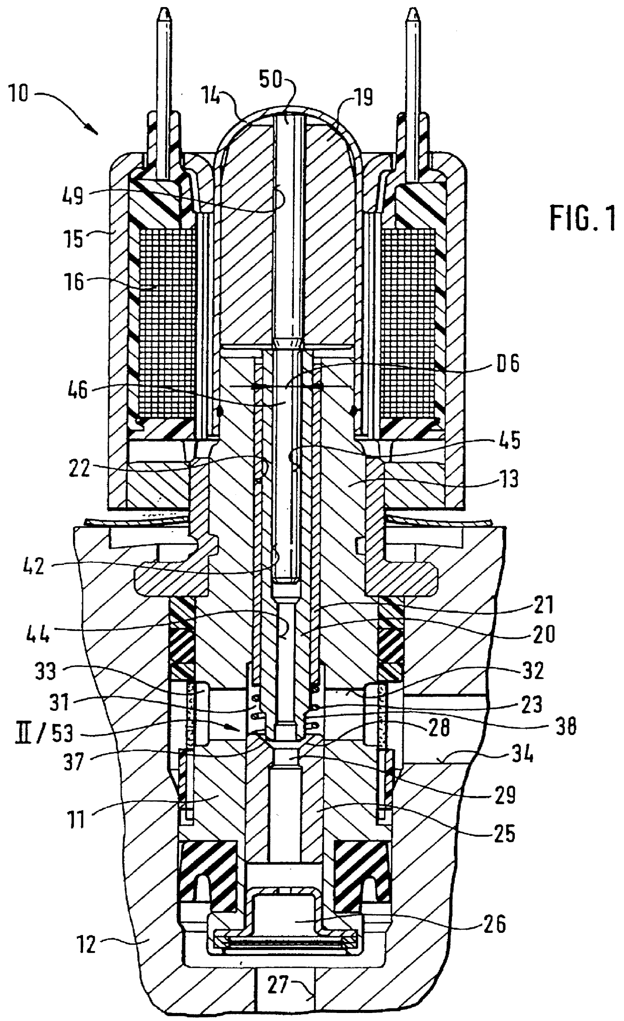
An electromagnetically actuated valve 10 shown in FIG. 1 of the drawing has a valve housing 11, with which it is received in a valve block 12. Outside the valve block 12, the valve housing 11 is continued in a pole core 13. An annular magnet coil 16, enveloped by a housing 15 that conducts magnetic flux, is slipped onto both the valve dome and the pole core 13.

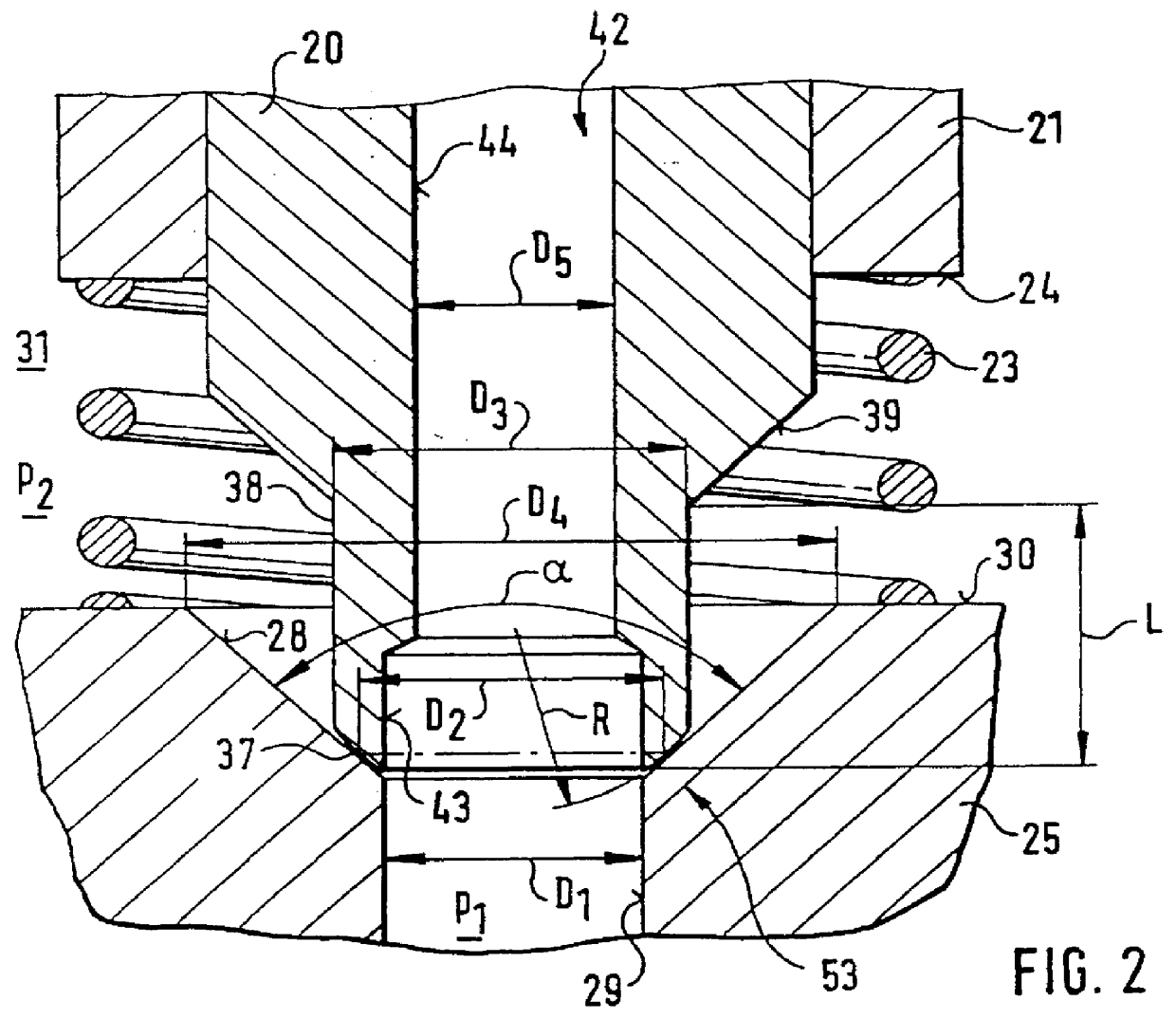
A longitudinally movable magnet armature 19 is located in the valve dome 14. It engages a tappet 20, onto which a sleeve 21 is press-fitted. The tappet 20 and the sleeve 21 are longitudinally movably received in a longitudinal bore 22 in the pole core 13 and the valve housing 11. A restoring spring 23 engages a face-end support face 24, remote from the armature, of the sleeve 21 (FIG. 2).

The restoring spring 23 is supported on a valve body 25 that is press-fitted into the valve housing 11 and drilled through longitudinally. The valve body communicates with a pressure medium inlet 26 of the valve 10, which in turn communicates ...


PUM


Abstract

PCT No. PCT / DE96 / 02160 Sec. 371 Date Aug. 7, 1998 Sec. 102(e) Date Aug. 7, 1998 PCT Filed Nov. 13, 1996 PCT Pub. No. WO97 / 28998 PCT Pub. Date Aug. 14, 1997The valve has a seat valve with a hollow-conical valve seat and a closing member in the form of a spherical layer on a longitudinally drilled tappet. An inflow bore communicating with a pressure medium inlet discharges centrally into the valve seat. The largely pressure-equalized tappet is engaged by a magnet armature acting on the seat valve in a closing manner and by a restoring spring acting in the opening direction. The valve embodied in principle as a switching valve is controllable into stable intermediate positions on the basis of the following provisions: the cone angle of the valve seat is at most 90 DEG ; the force at the closing member, originating in the restoring spring, is adapted such that it has a course that decreases monotonously with an increasing valve opening stroke (h); the magnet circuit of the valve is embodied such that the magnetic force (FM) exerted on the magnet armature and transmitted to the closing member is variable in infinitely graduated fashion and has a course that decreases monotonously with increasing valve opening stroke (h), the negative slope of which course is less quantitatively than that of the course of spring force.

Description

PRIOR ARTThe invention is based on an electromagnetically actuated valve for hydraulic motor vehicle brake systems.In slip-controlled hydraulic brake systems, valves are used which in their electromagnet-actuated closing position are subjected to very strong hydraulic opening forces. The electromagnetic circuit of these valves must therefore, in the valve closing position, bring to bear a holding-closed force on the magnet armature that is greater than the maximum hydraulic opening force plus the force of a restoring spring. A magnetic circuit designed in this way requires corresponding space for installation and with other disadvantages prevents the disposition of such valves in a space-saving, tight package.German Patent Application DE 31 26 246 A1 discloses a valve of this generic type in which to reduce the holding-closed force by means of pressure equilibrium operative at the tappet, a relatively short pin in the end portion toward the valve dome of the tappet that is passed th...

Claims


Application Information

Patent Timeline
IPC IPC(8): B60T8/34B60T15/00B60T15/02B60T8/36B60T8/50F16K31/06
CPCB60T8/363B60T8/365B60T15/028B60T8/5025B60T8/367B60T8/36
Inventor HOHL, GUENTHER
Owner ROBERT BOSCH GMBH
Why Eureka
Try Eureka